
User guide
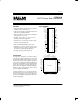

DS2181A
041995 4/32
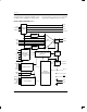
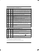
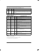
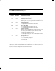
RECEIVE PIN DESCRIPTION (40–PIN DIP ONLY) Table 2B
PIN SYMBOL TYPE DESCRIPTION
21 RRA O Receive Remote Alarm. Transitions high when alarm detected; returns low when
alarm cleared.
22 RDMA O Receive Distant Multiframe Alarm. Transitions high when alarm detected; returns
low when alarm cleared.
23 RAF O Receive Alignment Frame. High during frames containing the frame alignment
signal, low otherwise.
24 RCLK I Receive Clock. 2.048 MHz primary clock.
25 RCHCLK O Receive Channel Clock. 256 KHz clock, identifies timeslot boundaries; useful for
serial-to-parallel conversion of channel data.
26 RSER O Receive Serial Data. Received NRZ data, updated on rising edges of RCLK.
27 RFSYNC O Receive Frame Sync. Trailing edge indicates start of frame.
28 RMSYNC O Receive Multiframe Sync. Low-high transition indicates start of CAS multiframe;
held high during frame 0.
29 RSD O Receive Signalling Data. Extracted timeslot 16 data; updated on rising edge of
RCLK.
30 RSTS O Receive Signalling Timeslot. High during timeslot 16 of every frame, low other-
wise.
31 RCSYNC O Receive CRC4 Sync. Low-high transition indicates start of CRC4 multiframe; held
high during CRC4 frames 0 thru 7 and held low during frames 8 through 15.
33 RST I Reset. Must be asserted during device power-up and when changing to/from the
hardware mode.
34
35
RPOS
RNEG
I Receive Bipolar Data. Sampled on falling edges of RCLK. Tie together to receive
NRZ data and disable BPV monitor circuitry.
36 RCL O Receive Carrier Loss. Low-high transition indicates loss of carrier.
37 RBV O Receive Bipolar Violation. Pulses high during detected bipolar violations.
38 RFER O Receive Frame Error. Pulses high when frame alignment, CAS multiframe align-
ment or CRC4 words received in error.
39 RLOS O Receive Loss of Sync. Indicates synchronizer status; high when frame, CAS and/
or CRC4 multiframe search underway, low otherwise.
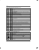
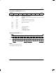
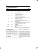
PORT PIN DESCRIPTION (40–PIN DIP ONLY) Table 3
PIN SYMBOL TYPE DESCRIPTION
14 INT O Receive Alarm Interrupt. Flags host controller during alarm conditions. Active low;
open drain output.
15 SDI I Serial Data In. Data for on-chip control registers; sampled on rising edge of SCLK.
16 SDO O Serial Data Out. Control and status data from on-chip registers. Updated on falling
edge of SCLK; tri-stated during port write or when CS
is high.
17 CS I Chip Select. Must be low to write or read the serial port.
18 SCLK I Serial Data Clock. Used to write or read the serial port registers.
19 SPS I Serial Port Select. Tie to V
DD
to select the serial port. Tie to V
SS
to select the
hardware mode.