
User guide

DS2181A
041995 22/32
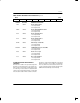
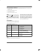
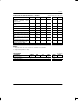
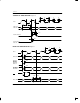
BVCR: BIPOLAR VIOLATION COUNT REGISTER Figure 20
(MSB) (LSB)
BVD7 BVD6 BVD5 BVD4 BVD3 BVD2 BVD1 BVD0
SYMBOL POSITION NAME AND DESCRIPTION
BVD7 BVCR.7 MSB of bipolar violation count.
BVD0 BVCR.0 LSB of bipolar violation count.
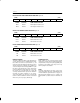
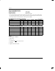
CECR: CRC4 ERROR COUNT REGISTER Figure 21
(MSB) (LSB)
CRC7 CRC6 CRC5 CRC4 CRC3 CRC2 CRC1 CRC0
SYMBOL POSITION NAME AND DESCRIPTION
CRC7 BVCR.7 MSB of CRC4 error count.
CRC0 BVCR.0 LSB of CRC4 error count.
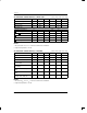
FECR: FRAME ERROR COUNT REGISTER Figure 22
(MSB) (LSB)
FE7 FE6 FE5 FE4 FE3 FE2 FE1 FE0
SYMBOL POSITION NAME AND DESCRIPTION
FE7 FECR.7 MSB of frame error count.
FE0 FECR.0 LSB of frame error count.
ERROR LOGGING
The BVCR, CECR and FECR contain 8-bit binary up
counters which increment on individual bipolar viola-
tions, CRC4 code word errors (when CCR.2 = 1), and
word errors in the frame alignment signal. Each counter
saturates at 255. Once saturated, each following error
occurrence will generate an interrupt (RIMR.0 = 1) until
the register is reprogrammed to a value other than FF
(hex). Presetting the registers allows the user to estab-
lish specific error count thresholds; the counter will
count up to saturation from the preset value. The BVCR
increments at all times (regardless of sync status),
except when HDB3 code words are received with
CCR.4=1. CECR and FECR increments are disabled
whenever resync is in progress (RLOS high).
ALARM OUTPUTS
Alarm conditions are also reported real time at alarm
outputs. These outputs can be used with off-chip logic to
complement the on-chip error reporting capability of the
DS2181A. In the hardware mode, they are the only
alarm reporting means available.
RLOS
The RLOS output indicates the status of the receive
synchronizer. When high, frame, CAS multiframe and/
or CRC4 multiframe synchronization is in progress. A
high-low transition indicates resync is complete. The
RLOS bit (RSR.1) is a latched version of the RLOS out-
put.