
User guide

DS2181A
041995 21/32
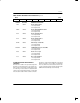
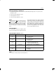
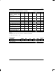
RIMR: RECEIVE INTERRUPT MASK REGISTER Figure 19
(MSB) (LSB)
RRA RDMA RSA1 RUA1 FSERR MFSERR RLOS ECS
SYMBOL POSITION NAME AND DESCRIPTION
RRA RIMR.7 Receive Remote Alarm
1 = Interrupt enabled
0 = Interrupt masked
RDMA RIMR.6 Receive Distant Multiframe Alarm
1 = Interrupt enabled
0 = Interrupt masked
RSA1 RIMR.5 Receive Signalling All 1’s
1 = Interrupt enabled
0 = Interrupt masked
RUA1 RIMR.4 Receive Unframed All 1’s
1 = Interrupt enabled
0 = Interrupt masked
FSERR RIMR.3 Frame Resync Criteria Met
1 = Interrupt enabled
0 = Interrupt masked
MFSERR RIMR.2 CAS Multiframe Resync Criteria Met
1 = Interrupt enabled
0 = Interrupt masked
RLOS RIMR.1 Receive Loss of Sync
1 = Interrupt enabled
0 = Interrupt masked
ECS RIMR.0 Error Count Saturation
1 = Interrupt enabled
0 = Interrupt masked
ALARM REPORTING AND INTERRUPT
SERVICING
Alarm and error conditions are reported at outputs and
the RSR. Use of the RSR and error count registers sim-
plifies system error monitoring. The RSR can be read in
one of two ways: a burst read does not disturb the RSR
contents; a direct read will clear all bits set in the RSR
unless the alarm condition which set them is still active.
Interrupts are enabled via the RIMR and are generated
whenever an alarm or error condition sets an RSR bit.
The host controller must service the transceiver in order
to clear an interrupt condition. Clearing the appropriate
RIMR bit will unconditionally clear an interrupt.