
User guide

DS2181A
041995 14/32
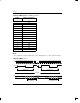
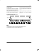
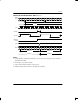
TXR: TRANSMIT EXTRA REGISTER Figure 10
(MSB) (LSB)
– – – – XB1 TDMA XB2 XB3
SYMBOL POSITION NAME AND DESCRIPTION
– TXR.7 Reserved; must be 0 for proper operation.
– TXR.6 Reserved; must be 0 for proper operation.
– TXR.5 Reserved; must be 0 for proper operation.
– TXR.4 Reserved; must be 0 for proper operation.
XB1 TXR.3 Extra Bit 1
TDMA TXR.2 Transmit Distant Multiframe Alarm
0 = Normal operation; bit 6 of timeslot 16 in frame 0 clear.
1 = Alarm condition; bit 6 of timeslot 16 in frame 0 set.
XB2 TXR.1 Extra Bit 2
XB3 TXR.0 Extra Bit 3
TRANSMIT EXTRA DATA
In the CAS mode, timeslot 16 of frame 0 contains the
multiframe alignment pattern, extra bits and the distant
multiframe alarm. When CAS is enabled (TCR.5 = 0),
the extra bits are sourced from TXR.0, TXR.1 and
TXR.3 (TCR.2 = 1) or the extra bits are sampled exter-
nally at TXD during the extra bit time (TCR.2 = 0). The
extra bits, alignment pattern and alarm signal are not uti-
lized in the CCS mode (TCR.5 = 1); input TSER over-
writes all timeslot 16 bit positions.
Reserved bit positions in the TXR must be set to 0 when
written; those bits can be 0 or 1 when read.
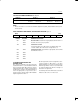
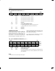
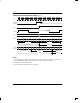
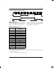
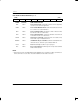
TIR1 - TIR4: TRANSMIT IDLE REGISTERS Figure 11
(MSB) (LSB)
TS7 TS6 TS5 TS4 TS3 TS2 TS1 TS0
1
TS15 TS14 TS13 TS12 TS11 TS10 TS9 TS8
TS23 TS22 TS21 TS20 TS19 TS18 TS17 TS16
1
TS31 TS30 TS29 TS28 TS27 TS26 TS25 TS24
SYMBOL POSITION NAME AND DESCRIPTION
TS31 TIR4.7 Transmit Idle Registers
TS0 TIR1.0 Each of these bit positions represents a timeslot in the outgoing stream at
TPOS and TNEG; when set, the contents of that timeslot are forced to idle
code (11010101).
NOTE:
1. TS0 and TS16 are not affected by the idle register.
TIR1
TIR2
TIR3
TIR4