
User Manual

DS2153Q
022697 23/48
will be informed when the signaling registers need to be
loaded with data. The user has 2 ms to load the data
before the old data will be retransmitted. Via the
CCR3.6 bit, the user has the option to use the Transmit
Channel Blocking Registers (TCBRs) to determine on a
channel by channel basis, which signaling bits are to be
inserted via the TSRs (the corresponding bit in the
TCBRs=1) and which are to be sourced from the TSER
pin (the corresponding bit in the TCBRs=0). See the
Transmit Data Flow diagram in Section 13 for more
details.
8.0 TRANSMIT IDLE REGISTERS
There is a set of five registers in the DS2153Q that can
be used to custom tailor the data that is to be transmitted
onto the E1 line, on a channel by channel basis. Each of
the 32 E1 channels can be forced to have a user defined
idle code inserted into them.
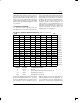
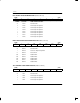
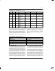
TIR1/TIR2/TIR3/TIR4: TRANSMIT IDLE REGISTERS (Address=26 to 29 Hex)
(MSB) (LSB)
CH8
CH7 CH6 CH5 CH4 CH3 CH2 CH1
CH16 CH15 CH14 CH13 CH12 CH11 CH10 CH9
CH24 CH23 CH22 CH21 CH20 CH19 CH18 CH17
CH32 CH31 CH30 CH29 CH28 CH27 CH26 CH25
SYMBOL POSITION NAME AND DESCRIPTION
CH32 TIR4.7 Transmit Idle Registers.
0=do not insert the Idle Code into this channel
CH1 TIR1.0 1=insert the Idle Code into this channel
NOTE:
If CCR3.5=1, then a zero in the TIRs implies that channel data is to be sourced from TSER and a one implies that
channel data is to be sourced from the RSER pin.
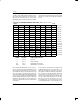
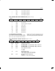
TIDR: TRANSMIT IDLE DEFINITION REGISTER (Address=2A Hex)
(MSB) (LSB)
TIDR7 TIDR6 TIDR5 TIDR4 TIDR3 TIDR2 TIDR1 TIDR0
SYMBOL POSITION NAME AND DESCRIPTION
TIDR7 TIDR.7 MSB of the Idle Code
TIDR0 TIDR.0 LSB of the Idle Code
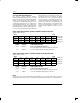
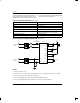
Each of the bit positions in the Transmit Idle Registers
(TIR1/TIR2/TIR3/TIR4) represent a timeslot in the out-
going frame. When these bits are set to a one, the corre-
sponding channel will transmit the Idle Code contained
in the Transmit Idle Definition Register (TIDR). In the
TIDR, the MSB is transmitted first. Via the CCR3.5 bit,
the user has the option to use the TIRs to determine on a
channel by channel basis, if data from the RSER pin
should be substituted for data from the TSER pin. In this
mode, if the corresponding bit in the TIRs is set to one,
then data will be sourced from the RSER pin. If the cor-
responding bit in the TIRs is set to zero, then data for
that channel will sourced from the TSER pin. See the
Transmit Data Flow diagram in Section 13 for more
details.
TIR1 (26)
TIR2 (27)
TIR3 (28)
TIR4 (29)