
User Manual

DS2153Q
022697 11/48
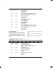
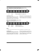
THDB3 CCR1.6 Transmit HDB3 Enable.
0=HDB3 disabled
1=HDB3 enabled
TG802 CCR1.5 Transmit G.802 Enable. See Section 13 for details.
0=do not force TCHBLK high during bit 1 of timeslot 26
1=force TCHBLK high during bit 1 of timeslot 26
TCRC4 CCR1.4 Transmit CRC4 Enable.
0=CRC4 disabled
1=CRC4 enabled
RSM CCR1.3 Receive Signaling Mode Select.
0=CAS signaling mode
1=CCS signaling mode
RHDB3 CCR1.2 Receive HDB3 Enable.
0=HDB3 disabled
1=HDB3 enabled
RG802 CCR1.1 Receive G.802 Enable. See Section 13 for details.
0=do not force RCHBLK high during bit 1 of timeslot 26
1=force RCHBLK high during bit 1 of timeslot 26
RCRC4 CCR1.0 Receive CRC4 Enable.
0=CRC4 disabled
1=CRC4 enabled
FRAMER LOOPBACK
When CCR1.7 is set to a one, the DS2153Q will enter a
Framer LoopBack (FLB) mode. This loopback is useful
in testing and debugging applications. In FLB, the
DS2153Q will loop data from the transmit side back to
the receive side. When FLB is enabled, the following
will occur:
1. data will be transmitted as normal at TTIP and
TRING
2. data off the E1 line at RTIP and RRING will be
ignored
3. the RCLK output will be replaced with the TCLK
input.
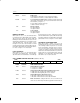
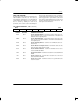
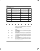
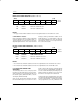
CCR2: COMMON CONTROL REGISTER 2 (Address=1A Hex)
(MSB) (LSB)
ECUS
VCRFS AAIS ARA RSERC LOTCMC RLB LLB
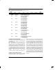
SYMBOL POSITION NAME AND DESCRIPTION
ECUS CCR2.7 Error Counter Update Select.
0=update error counters once a second
1=update error counters every 62.5 ms (500 frames)
VCRFS CCR2.6 VCR Function Select.
0=count BiPolar Violations (BPVs)
1=count Code Violations (CVs)
AAIS CCR2.5 Automatic AIS Generation.
0=disabled
1=enabled
ARA CCR2.4 Automatic Remote Alarm Generation.
0=disabled
1=enabled