
Owner manual

DS2151Q
022697 25/46
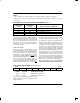
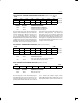
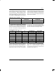
TTR1/TTR2/TTR3: TRANSMIT TRANSPARENCY REGISTERS (Address=39 to 3B Hex)
(MSB) (LSB)
CH8
CH7 CH6 CH5 CH4 CH3 CH2 CH1
CH16 CH15 CH14 CH13 CH12 CH11 CH10 CH9
CH24 CH23 CH22 CH21 CH20 CH19 CH18 CH17
SYMBOL POSITION NAME AND DESCRIPTION
CH24 TTR3.7 Transmit Transparency Registers.
0=this DS0 channel is not transparent
CH1 TTR1.0 1=this DS0 channel is transparent
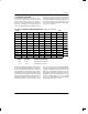
Each of the bit positions in the Transmit Transparency
Registers (TTR1/TTR2/TTR3) represent a DS0 chan-
nel in the outgoing frame. When these bits are set to a
one, the corresponding channel is transparent (or
clear). If a DS0 is programmed to be clear, no Robbed–
Bit signaling will be inserted nor will the channel have Bit
7 stuffing performed. However, in the D4 framing mode,
bit 2 will be overwritten by a zero when a Yellow Alarm is
transmitted. Also the user has the option to prevent the
TTR registers from determining which channels are to
have Bit 7 stuffing performed. If the TCR2.0 and
TCR1.3 bits are set to one, then all 24 T1 channels will
have Bit 7 stuffing performed on them regardless of how
the TTR registers are programmed. In this manner, the
TTR registers are only affecting which channels are to
have Robbed–Bit signaling inserted into them. Please
see Figure 13–9 for more details.
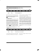
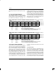
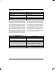
TIR1/TIR2/TIR3: TRANSMIT IDLE REGISTERS (Address=3C to 3E Hex)
(MSB) (LSB)
CH8 CH7 CH6 CH5 CH4 CH3 CH2 CH1
CH16 CH15 CH14 CH13 CH12 CH11 CH10 CH9
CH24 CH23 CH22 CH21 CH20 CH19 CH18 CH17
SYMBOL POSITION NAME AND DESCRIPTION
CH24 TIR3.7 Transmit Idle Registers.
0=do not insert the Idle Code into this DS0 channel
CH1 TIR1.0 1=insert the Idle Code into this channel
TIDR: TRANSMIT IDLE DEFINITION REGISTER (Address=3F Hex)
(MSB) (LSB)
TIDR7 TIDR6 TIDR5 TIDR4 TIDR3 TIDR2 TIDR1 TIDR0
SYMBOL POSITION NAME AND DESCRIPTION
TIDR7 TIDR.7 MSB of the Idle Code
TIDR0 TIDR.0 LSB of the Idle Code
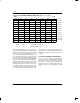
Each of the bit positions in the Transmit Idle Registers
(TIR1/TIR2/TIR3) represent a DS0 channel in the out-
going frame. When these bits are set to a one, the corre-
sponding channel will transmit the Idle Code contained
in the Transmit Idle Definition Register (TIDR).
Robbed–Bit signaling and Bit 7 stuffing will occur over
the programmed Idle Code unless the DS0 channel is
TTR1 (39)
TTR2 (3A)
TTR3 (3B)
TIR1 (3C)
TIR2 (3D)
TIR3 (3E)