
Owner's manual


DS21455/DS21458 Quad T1/E1/J1 Transceivers
34 of 270
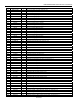
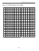
Table 5-2. DS21458 PIN DESCRIPTION
PIN NAME TYPE FUNCTION
H2 A0 I Address Bus Bit 0 (Lsb)
E10 A1 I Address Bus Bit 1
H3 A2 I Address Bus Bit 2
G4 A3 I Address Bus Bit 3
N7 A4 I Address Bus Bit 4
B9 A5 I Address Bus Bit 5
T7 A6 I Address Bus Bit 6
G2 A7/ALE (AS) I Address Bus Bit 7 (Msb)/Address Latch Enable
H6 A8 I Address Bus Bit 8
J11 A9 I Address Bus Bit 9
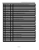
J5 BPCLK1 O Backplane Clock, Transceiver 1
H13 BPCLK2 O Backplane Clock, Transceiver 2
E8 BPCLK3 O Backplane Clock, Transceiver 3
N9 BPCLK4 O Backplane Clock, Transceiver 4
B10 BTS I Bus Type Select (0 = Intel/1 = Motorola)
M8
CS
I Chip Select
P8 D0/AD0 I/O Data Bus Bit 0/Address/Data Bus Bit 0 (Lsb)
D10 D1/AD1 I/O Data Bus Bit 1/ Address/Data Bus Bit 1
N8 D2/AD2 I/O Data Bus Bit 2/Address/Data Bus Bit 2
P7 D3/AD3 I/O Data Bus Bit 3/Address/Data Bus Bit 3
M7 D4/AD4 I/O Data Bus Bit 4/Address/Data Bus Bit 4
R7 D5/AD5 I/O Data Bus Bit 5/Address/Data Bus Bit 5
G1 D6/AD6 I/O Data Bus Bit 6/Address/Data Bus Bit 6
G3 D7/AD7 I/O Data Bus Bit 7/Address/Data Bus Bit 7 (Msb)
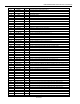
P4 DVDD — Digital Positive Supply
P5 DVDD — Digital Positive Supply
P6 DVDD — Digital Positive Supply
C11 DVDD — Digital Positive Supply
C12 DVDD — Digital Positive Supply
C13 DVDD — Digital Positive Supply
D3 DVDD — Digital Positive Supply
E3 DVDD — Digital Positive Supply
F3 DVDD — Digital Positive Supply
L14 DVDD — Digital Positive Supply
M14 DVDD — Digital Positive Supply
N14 DVDD — Digital Positive Supply
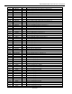
N4 DVSS — Digital Signal Ground
N5 DVSS — Digital Signal Ground
N6 DVSS — Digital Signal Ground
D11 DVSS — Digital Signal Ground
D12 DVSS — Digital Signal Ground
D13 DVSS — Digital Signal Ground
D4 DVSS — Digital Signal Ground
E4 DVSS — Digital Signal Ground
F4 DVSS — Digital Signal Ground
L13 DVSS — Digital Signal Ground
M13 DVSS — Digital Signal Ground
N13 DVSS — Digital Signal Ground
H8 ESIBRD I/O Extended System Information Bus Read
J8 ESIBS0 I/O Extended System Information Bus 0