
Owner's manual

DS21455/DS21458 Quad T1/E1/J1 Transceivers
220 of 270
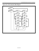
35.1 Instruction Register
The instruction register contains a shift register as well as a latched parallel output and is 3 bits in length.
When the TAP controller enters the shift-IR state, the instruction shift register will be connected between
JTDI and JTDO. While in the shift-IR state, a rising edge on JTCLK with JTMS LOW will shift the data
one stage towards the serial output at JTDO. A rising edge on JTCLK in the exit1-IR state or the exit2-IR
state with JTMS HIGH will move the controller to the update-IR state. The falling edge of that same
JTCLK will latch the data in the instruction shift register to the instruction parallel output. Instructions
supported by the DS21455/DS21458 and their respective operational binary codes are shown in
Table 35-1.
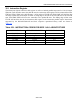
Table 35-1. INSTRUCTION CODES FOR IEEE 1149.1 ARCHITECTURE
INSTRUCTION SELECTED REGISTER INSTRUCTION CODES
SAMPLE/PRELOAD Boundary Scan 010
BYPASS Bypass 111
EXTEST Boundary Scan 000
CLAMP Bypass 011
HIGH-Z Bypass 100
IDCODE Device Identification 001