
Owner's manual


DS21455/DS21458 Quad T1/E1/J1 Transceivers
174 of 270
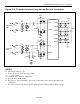
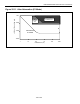
Figure 25-6. Protected Interface Using Internal Receive Termination
NOTES:
1) All resistor values are ±1%.
2) X1 and X2 are very low DCR transformers
3) C1 = 1µF ceramic.
4) S1 and S2 are 6V transient suppressers.
5) D1 to D8 are Schottky diodes.
6) The fuses, F1–F4, are optional to prevent AC power-line crosses from compromising the
transformers.
7) The 68mF is used to keep the local power-plane potential within tolerance during a surge.
TTIP
TRING
RTIP
RRING
DVDD
TVDD
RVDD
V
DD
V
DD
DVSS
TVSS
RVSS
DS21455/458
68mF
2:1
1:1
D1 D2
D3
D4
C1
F1
F2
F3
F4
S1
0.1mF
0.1mF
0.1mF
0.01mF
X1
X2
TRANSMIT
LINE
RECEIVE
LINE
0.1mF
10mF
10mF
+
+
+
0.1mF
S2
60W
60W
V
DD
D5 D6
D7
D8
0.1mF