
Instruction Manual

______________________________________________________________________________________ 59
DS1876
SFP Controller with Dual LDD Interface
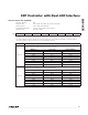
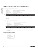
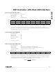
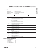
Table 02h, Register C1h: PW_ENB
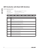
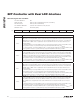
Table 02h, Register C2h–C5h: RESERVED
FACTORY DEFAULT 03h
READ ACCESS PW2 or (PW1 and RWTBL2) or (PW1 and RTBL2)
WRITE ACCESS PW2 or (PW1 and RWTBL2)
A2h AND B2h MEMORY Common A2h and B2h memory location
MEMORY TYPE Nonvolatile (SEE)
C1h RWTBL46 RTBL1C RTBL2 RTBL1A RTBL1B WPW1 WAUXAU WAUXBU
BIT 7 BIT 0
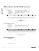
BIT 7
RWTBL46: Tables 04h and 06h.
0 = (default) Read and write access for PW2 only.
1 = Read and write access for PW1 and PW2.
BIT 6
RTBL1C: Table 01h or Table 05h, Registers F8h–FFh. Table address is dependent on MASK bit
(Table 02h, Register 88h).
0 = (default) Read and write access for PW2 only.
1 = Read access for PW1 and PW2.
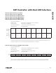
BIT 5
RTBL2: Table 02h.
0 = (default) Read and write access for PW2 only.
1 = Read access for PW1 and PW2.
BIT 4
RTBL1A: Table 01h, Registers 80h–BFh.
0 = (default) Read and write access for PW2 only.
1 = Read access for PW1 and PW2.
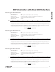
BIT 3
RTBL1B: Table 01h, Registers C0h–F7h.
0 = (default) Read and write access for PW2 only.
1 = Read access for PW1 and PW2.
BIT 2
WPW1: Register PW1 (Table 02h, Registers B0h–B3h). For security purposes these registers are
not readable.
0 = (default) Write access for PW2 only.
1 = Write access for PW1 and PW2.
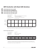
BIT 1
WAUXAU: Auxiliary memory, Registers 00h–7Fh. All users can read this area.
0 = Write access for PW2 only.
1 = (default) Write access for user, PW1, and PW2.
BIT 0
WAUXBU: Auxiliary memory, Registers 80h–FFh. All users can read this area.
0 = Write access for PW2 only.
1 = (default) Write access for user, PW1, and PW2.
FACTORY DEFAULT
READ ACCESS N/A
WRITE ACCESS N/A
A2h AND B2h MEMORY N/A
MEMORY TYPE N/A
These registers are reserved.