
Instruction Manual
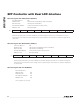

54 _____________________________________________________________________________________
DS1876
SFP Controller with Dual LDD Interface
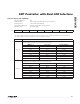
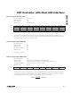
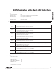
Table 02h, Register A2h–A3h: V
CC
OFFSET
Table 02h, Register A4h–A7h: RESERVED
Table 02h, Register A8h–A9h: BMON2 OFFSET
Table 02h, Register AAh–ABh: PMON2 OFFSET
Table 02h, Register ACh–ADh: BMON1 OFFSET
Table 02h, Register AEh–AFh: PMON1 OFFSET
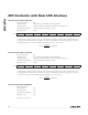
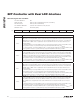
Table 02h, Register B0h–B3h: PW1
FACTORY DEFAULT 00h
READ ACCESS PW2 or (PW1 and RWTBL2) or (PW1 and RTBL2)
WRITE ACCESS PW2 or (PW1 and RWTBL2)
A2h AND B2h MEMORY Common A2h and B2h memory location
MEMORY TYPE Nonvolatile (SEE)
A2h, A4h,
A6h, A8h,
AAh, ACh,
AEh
S S 2
15
2
14
2
13
2
12
2
11
2
10
A3h, A5h,
A7h, A9h,
ABh, ADh,
AFh
2
9
2
8
2
7
2
6
2
5
2
4
2
3
2
2
BIT 7 BIT 0
Allows for offset control of these voltage measurements if desired. This number is two’s complement.
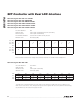
FACTORY DEFAULT FFFF FFFFh
READ ACCESS N/A
WRITE ACCESS PW2 or (PW1 and WPW1)
MEMORY TYPE Nonvolatile (SEE)
B0h 2
31
2
30
2
29
2
28
2
27
2
26
2
25
2
24
B1h 2
23
2
22
2
21
2
20
2
19
2
18
2
17
2
16
B2h 2
15
2
14
2
13
2
12
2
11
2
10
2
9
2
8
B3h 2
7
2
6
2
5
2
4
2
3
2
2
2
1
2
0
BIT 7 BIT 0
The PWE value is compared against the value written to this location to enable PW1 access. At power-on, the
PWE value is set to all ones. Thus, writing these bytes to all ones grants PW1 access on power-on without writing
the password entry. All reads of this register are 00h.