
Instruction Manual

36 _____________________________________________________________________________________
DS1876
SFP Controller with Dual LDD Interface
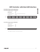
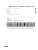
Lower Memory, Register 70h: ALARM
3
POWER-ON VALUE 10h
READ ACCESS All
WRITE ACCESS N/A
A2h AND B2h MEMORY Different A2h and B2h memory locations
MEMORY TYPE Volatile
70h TEMP HI TEMP LO VCC HI VCC LO BMON HI BMON LO PMON HI PMON LO
BIT 7 BIT 0
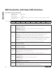
BIT 7
TEMP HI: High alarm status for temperature measurement.
0 = (default) Last measurement was equal to or below threshold setting.
1 = Last measurement was above threshold setting.
BIT 6
TEMP LO: Low alarm status for temperature measurement.
0 = (default) Last measurement was equal to or above threshold setting.
1 = Last measurement was below threshold setting.
BIT 5
VCC HI: High alarm status for V
CC
measurement.
0 = (default) Last measurement was equal to or below threshold setting.
1 = Last measurement was above threshold setting.
BIT 4
VCC LO: Low alarm status for V
CC
measurement. This bit is set when the V
CC
supply is below
the POA trip point value. It clears itself when a V
CC
measurement is completed and the value is
above the low threshold.
0 = Last measurement was equal to or above threshold setting.
1 = (default) Last measurement was below threshold setting.
BIT 3
BMON HI: High alarm status for BMON measurement.
0 = (default) Last measurement was equal to or below threshold setting.
1 = Last measurement was above threshold setting.
BIT 2
BMON LO: Low alarm status for BMON measurement.
0 = (default) Last measurement was equal to or above threshold setting.
1 = Last measurement was below threshold setting.
BIT 1
PMON HI: High alarm status for PMON measurement.
0 = (default) Last measurement was equal to or below threshold setting.
1 = Last measurement was above threshold setting.
BIT 0
PMON LO: Low alarm status for PMON measurement.
0 = (default) Last measurement was equal to or above threshold setting.
1 = Last measurement was below threshold setting.