
Instruction Manual

______________________________________________________________________________________ 29
DS1876
SFP Controller with Dual LDD Interface
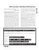
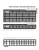
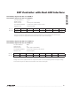
Lower Memory, Register 08h–09h: V
CC
ALARM HI
Lower Memory, Register 0Ch–0Dh: V
CC
WARN HI
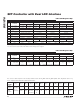
Lower Memory, Register 0Ah–0Bh: V
CC
ALARM LO
Lower Memory, Register 0Eh–0Fh: V
CC
WARN LO
FACTORY DEFAULT FFFFh
READ ACCESS All
WRITE ACCESS PW2 or (PW1 and WLOWER)
A2h AND B2h MEMORY Common A2h and B2h memory location
MEMORY TYPE Nonvolatile (SEE)
08h, 0Ch 2
15
2
14
2
13
2
12
2
11
2
10
2
9
2
8
09h, 0Dh 2
7
2
6
2
5
2
4
2
3
2
2
2
1
2
0
BIT 7 BIT 0
Voltage measurement updates above this unsigned threshold set its corresponding alarm or warning bit.
Voltage measurements equal to or below this threshold clear its alarm or warning bit.
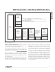
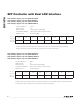
FACTORY DEFAULT 0000h
READ ACCESS All
WRITE ACCESS PW2 or (PW1 and WLOWER)
A2h AND B2h MEMORY Common A2h and B2h memory location
MEMORY TYPE Nonvolatile (SEE)
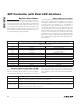
0Ah, 0Eh 2
15
2
14
2
13
2
12
2
11
2
10
2
9
2
8
0Bh, 0Fh 2
7
2
6
2
5
2
4
2
3
2
2
2
1
2
0
BIT 7 BIT 0
Voltage measurement updates below this unsigned threshold set its corresponding alarm or warning bit. Voltage
measurements equal to or above this threshold clear its alarm or warning bit.