
Instruction Manual

______________________________________________________________________________________ 27
DS1876
SFP Controller with Dual LDD Interface
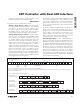
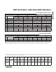
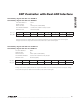
Table 05h Register Map
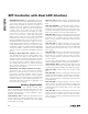
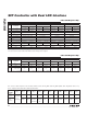
Table 06h Register Map
<C> or <_/C> = Common, <D> or <_/D> = Different, <M> or <_/M> = Mixture of common and different.
Note: Table 05h is empty by default. It can be configured to contain the alarm and warning enable bytes from Table 01h,
Registers F8h–FFh with the MASK bit enabled (Table 02h, Register 88h). In this case Table 01h is empty.
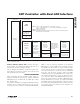
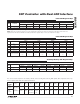
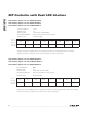
Auxiliary Memory A0h Register Map
<C> or <_/C> = Common, <D> or <_/D> = Different, <M> or <_/M> = Mixture of common and different.
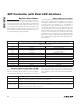
The access codes represent the factory default values of PW_ENA and PW_ENB (Table 02h, Registers C0h–C1h).
These registers also allow for custom permissions.
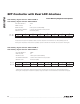
<C> or <_/C> = Common, <D> or <_/D> = Different, <M> or <_/M> = Mixture of common and different.
TABLE 05h
ROW
(HEX)
ROW NAME
WORD 0 WORD 1 WORD 2 WORD 3
BYTE 0/8 BYTE 1/9 BYTE 2/A BYTE 3/B BYTE 4/C BYTE 5/D BYTE 6/E BYTE 7/F
80–F7 EMPTY EMPTY EMPTY EMPTY EMPTY EMPTY EMPTY EMPTY EMPTY
F8
<7/M>
ALARM ENABLE
<M>
ALARM EN
3
RESERVED
<D>
ALARM EN
1
RESERVED
<M>
WARN EN
3
RESERVED RESERVED RESERVED
TABLE 06h (APC LUT)
ROW
(HEX)
ROW NAME
WORD 0 WORD 1 WORD 2 WORD 3
BYTE 0/8 BYTE 1/9 BYTE 2/A BYTE 3/B BYTE 4/C BYTE 5/D BYTE 6/E BYTE 7/F
80–C7
<8/D>
LUT6 APC LUT APC LUT APC LUT APC LUT APC LUT APC LUT APC LUT APC LUT
C8–DF EMPTY EMPTY EMPTY EMPTY EMPTY EMPTY EMPTY EMPTY EMPTY
E0
<8/D>
HBATH HBATH LUT HBATH LUT HBATH LUT HBATH LUT HBATH LUT HBATH LUT HBATH LUT HBATH LUT
E8
<8/D>
HTXP HTXP LUT HTXP LUT HTXP LUT HTXP LUT HTXP LUT HTXP LUT HTXP LUT HTXP LUT
F0
<8/D>
LTXP LTXP LUT LTXP LUT LTXP LUT LTXP LUT LTXP LUT LTXP LUT LTXP LUT LTXP LUT
F8
<8/D>
APC OFFSET
APC OFFSET
LUT
APC OFFSET
LUT
APC OFFSET
LUT
APC OFFSET
LUT
APC OFFSET
LUT
APC OFFSET
LUT
APC OFFSET
LUT
APC OFFSET
LUT
AUXILIARY MEMORY (A0h)
ROW
(HEX)
ROW NAME
WORD 0 WORD 1 WORD 2 WORD 3
BYTE 0/8 BYTE 1/9 BYTE 2/A BYTE 3/B BYTE 4/C BYTE 5/D BYTE 6/E BYTE 7/F
00–7F
<5>
AUX EE EE EE EE EE EE EE EE EE
80–FF
<5>
AUX EE EE EE EE EE EE EE EE EE
ACCESS
CODE
<0/_> <1/_> <2/_> <3/_> <4/_> <5/_> <6/_> <7/_> <8/_> <9/_> <10/_> <11/_>
Read
Access
See each
bit/byte
separately
All All All PW2 All N/A PW1 PW2 N/A PW2 All
Write
Access
PW2 N/A
All and
DS1876
Hardware
PW2 +
mode
bit
All All PW1 PW2 PW2 N/A PW1