
User Manual


DS1775
7 of 13
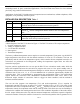
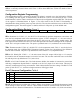
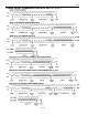
Thermometer Resolution Configuration Table 5
R1 R0 Thermometer Resolution Max Conversion Time
0 0 9-bit 0.1875s
0 1 10-bit 0.375s
1 0 11-bit 0.75s
1 1 12-bit 1.5s
Thermostat Setpoints Programming
The thermostat registers (T
OS
and T
HYST
) can be programmed or read via the 2–wire interface. T
OS
is
accessed by setting the DS1775 data pointer to the 03h location, and to the 02h location for T
HYST
.
The format of the T
OS
and T
HYST
registers is identical to that of the Thermometer register; that is, 12–bit
2’s complement representation of the temperature in °C. The user can program the number of bits (9, 10,
11, or 12) for each T
OS
and T
HYST
that corresponds to the thermometer resolution mode chosen. For
example, if the 9–bit mode is chosen the 3 least significant bits of T
OS
and T
HYST
will be ignored by the
thermostat comparator. The format for both T
OS
and T
HYST
is shown in Table 6. The power–up default
for T
OS
is 80°C and for T
HYST
is 75°C.
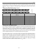
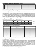
Thermostat Setpoint (T
OS
/T
HYST
) Format Table 6
S2
6
2
5
2
4
2
3
2
2
2
1
2
0
MSB
MSb (UNIT = °C) LSb
2
-1
2
-2
2
-3
2
-4
0000LSB
TEMPERATURE/DATA RELATIONSHIPS
TEMP DIGITAL OUTPUT
(Binary)
DIGITAL OUTPUT (Hex)
+80°C
0101 0000 0000 0000 5000h
+75°C
0100 1011 0000 0000 4B00h
+10.125°C
0000 1010 0010 0000 0A20h
+0.5°C
0000 0000 1000 0000 0080h
+0°C
0000 0000 0000 0000 0000h
-0.5°C
1111 1111 1000 0000 FF80h
-10.125°C
1111 0101 1110 0000 F5E0h
-25.0625°C
1110 0110 1111 0000 E6F0h
-55°C
1100 1001 0000 0000 C900h
If the user does not wish to take advantage of the thermostat capabilities of the DS1775, the 24 bits can be
used for general storage of system data that need not be maintained following a power loss.
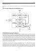
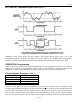
2–WIRE SERIAL DATA BUS
The DS1775 supports a bi–directional 2-wire bus and data transmission protocol. A device that sends data
onto the bus is defined as a transmitter, and a device receiving data as a receiver. The device that controls
the message is called a “master”. The devices that are controlled by the master are “slaves”. The bus must
be controlled by a master device which generates the serial clock (SCL), controls the bus access, and
generates the START and STOP conditions. The DS1775 operates as a slave on the two–wire bus.
Connections to the bus are made via the open–drain I/O lines SDA and SCL.
The following bus protocol has been defined (See Figure 4):
• Data transfer may be initiated only when the bus is not busy.