
User Manual
DS1220Y
091295 6/8
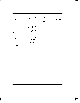
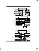
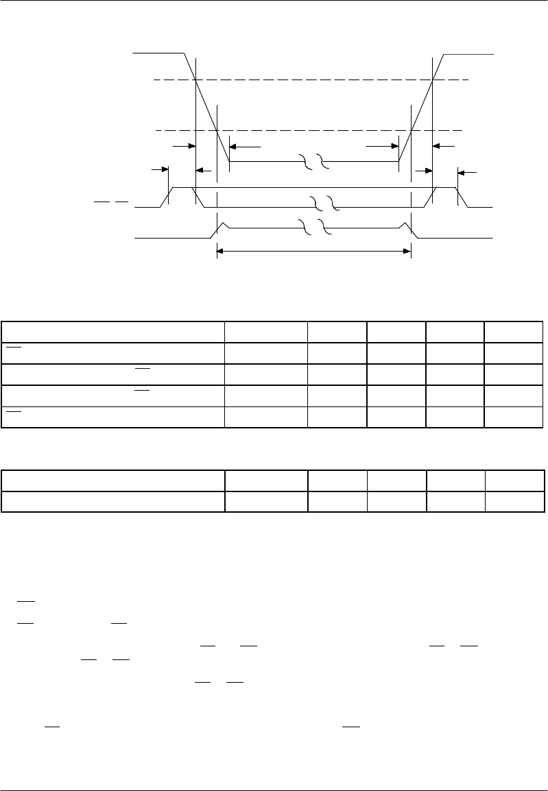
POWER-DOWN/POWER-UP CONDITION
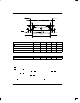
DATA RETENTION TIME
t
DR
t
F
t
PD
WE, CE
V
CC
LEAKAGE CURRENT
I
L
SUPPLIED FROM
LITHIUM CELL
t
R
t
REC
V
TP
3.2V
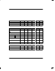
POWER-DOWN/POWER-UP TIMING
PARAMETER SYMBOL MIN MAX UNITS NOTES
CE at V
IH
before Power-Down t
PD
0 µ s 10
V
CC
Slew from V
TP
to 0V (CE at V
IH
) t
F
100 µs
V
CC
Slew from 0V to V
TP
(CE at V
IH
) t
R
0 µs
CE at V
IH
after Power-Up t
REC
2 ms
(t
A
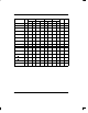
= 25°C)
PARAMETER SYMBOL MIN MAX UNITS NOTES
Expected Data Retention Time t
DR
10 years 9
WARNING:
Under no circumstance are negative undershoots, of any amplitude, allowed when device is in battery backup mode.
NOTES:
1. WE is high for a read cycle.
2. OE
= V
IH
or V
IL
. If OE = V
IH
during a write cycle, the output buffers remain in a high impedance state.
3. t
WP
is specified as the logical AND of CE and WE. t
WP
is measured from the latter of CE or WE going low to
the earlier of CE or WE going high.
4. t
DS
are measured from the earlier of CE or WE going high.
5. These parameters are sampled with a 5 pF load and are not 100% tested.
6. If the CE
low transition occurs simultaneously with or later than the WE low transition in write cycle 1, the
output buf fers remain in a high impedance state during this period.