
User guide


ADIS16250/ADIS16255
Rev. B | Page 13 of 20
PROGRAMMING AND CONTROL
CONTROL REGISTER OVERVIEW
The ADIS16250/ADIS16255 offer many programmable features
controlled by writing commands to the appropriate control
registers using the SPI.
Tabl e 8 provides a summary of these
control registers, which controls the operation of the following
parameters:
• Calibration
• Global commands
• Operational control
• Sample rate
• Power management
• Digital filtering
• Dynamic range
• DAC output
• Digital I/O
• Operational status and diagnostics
• Self-test
• Status conditions
• Alarms
CONTROL REGISTER STRUCTURE
The ADIS16250/ADIS16255 uses a temporary, RAM-based
memory structure to facilitate the control registers displayed in
Tabl e 8. The start-up configuration is stored in a flash memory
structure that automatically loads into the control registers
during the start-up sequence. Each nonvolatile register has a
corresponding flash memory location, for storing the latest
configuration contents. Since flash memory has endurance
limitations, the contents of each nonvolatile register must be
manually stored to flash (note that the contents of the control
register contents are only nonvolatile when they are stored to
flash). The manual flash update command, made available
in the COMMAND register, provides this function. The
ENDURANCE register provides a counter that allows for
memory reliability management against the 20,000-write cycle
specification.
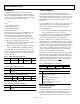
Table 8. Control Register Memory Map
Register Name Type Volatility Address Bytes Function Reference Table
GYRO_OFF R/W Nonvolatile 0x15, 0x14 2 Gyroscope bias offset factor Table 9, Table 10
GYRO_SCALE R/W Nonvolatile 0x17, 0x16 2 Gyroscope scale factor Table 11, Table 12
0x18 to 0x1F 8 Reserved
ALM_MAG1 R/W Nonvolatile 0x21, 0x20 2 Alarm 1 amplitude threshold and polarity Table 31, Table 32
ALM_MAG2 R/W Nonvolatile 0x23, 0x22 2 Alarm 2 amplitude threshold and polarity Table 35, Table 36
ALM_SMPL1 R/W Nonvolatile 0x25, 0x24 2 Alarm 1 sample period Table 33, Table 34
ALM_SMPL2 R/W Nonvolatile 0x27, 0x26 2 Alarm 2 sample period Table 37, Table 38
ALM_CTRL R/W Nonvolatile 0x29, 0x28 2 Alarm control register Table 39, Table 40
0x2A to 0x2F 6 Reserved
AUX_DAC R/W Volatile 0x31, 0x30 2 Auxiliary DAC data Table 21, Table 22
GPIO_CTRL R/W Volatile 0x33, 0x32 2 Auxiliary digital I/O control register Table 23, Table 24
MSC_CTRL R/W Nonvolatile
1
0x35, 0x34 2 Miscellaneous control register Table 26, Table 27
SMPL_PRD R/W Nonvolatile 0x37, 0x36 2 ADC sample period control Table 15, Table 16
SENS/AVG R/W Nonvolatile 0x39, 0x38 2
Defines the dynamic range (sensitivity setting)
and the number of taps for the digital filter
Table 19, Table 20
SLP_CNT R/W Volatile 0x3B, 0x3A 2
Counter used to determine length of power-
down mode
Table 17, Table 18
STATUS R Volatile 0x3D, 0x3C 2 System status register Table 28, Table 29
COMMAND W N/A 0x3F, 0x3E 2 System command register Table 13, Table 14
1
The contents of the upper byte are nonvolatile; the contents of the lower byte are volatile.