
Owner's manual


19
5440A–IMAGE–10/05
[Preliminary] ATMOS -2M60/2M30
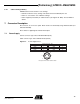
6.4.2 Camera Settings Memory
ATMOS cameras have 5 banks to save settings:
• Bank 0 contains the factory settings. This bank cannot be modified by the user
• Bank 1 to 4 are used to store 4 different settings
• Bank 1 might be protected by an advanced user (see Register @ 104H). Contact Atmel for
details
7. Connector Description
All connectors are on the rear panel. Better results are obtained by using shielded cables (foil
and braid shielded).
Note: cables for digital signals shall be twisted pairs.
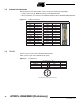
7.1 Power Supply
Camera connector type: Hirose HR10A-7R-6PB (male)
Cable connector type: Hirose HR10A-7P-6S (female)
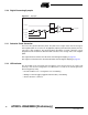
Figure 7-1. Power Supply Pinout
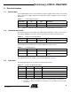
Power Connector : J01
Signal Pin Signal Pin
PWR 1 GND 4
NC 2 NC 5
PWR 3 GND 6
1
2
3
6
5
4
Receptacle Viewed from Camera Back