
User Manual


5
5429B–IMAGE–04/05
[Preliminary] ATMOS -1M60/1M30
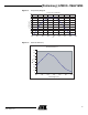
3. Camera Description
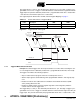
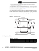
Figure 3-1. Camera Synoptic
The camera is based on a single tap CMOS sensor which delivers a 12-bit digital video signal at
its output. An FPGA has been implemented for image processing (FPN column correction, con-
version LUT, contrast expansion). The camera is powered by a single DC power supply from
12V to 24V. The functional interface (data and control) is provided with the CameraLink inter-
face. The camera uses the base configuration of the CameraLink standard.
Note: DVAL permanently tied to 1 (high) level.
Data can be delivered on a single channel or two de-multiplexed channels. The data format con-
figuration might be in 12-bit, 10-bit, or 8-bit. It is possible to use external triggers with the camera
(CC1 signal or TTL_IO trigger input) in different trigger modes see ”Synchronization Modes” on
page 6 The camera configuration and settings are done via the CameraLink serial communica-
tion. This interface is used for:
• Gain and offset setting
• Data output format
• Synchronization modes: free-run or external trigger modes
• Shutter time
• Test pattern generation
• Upload and download of correction data (FPN column correction, LUT)
CMOS
SENSOR
Microcontroller
CameraLink
Transceiver
TX
RX
Power Supplies
DC power
Camera Link
I/F
Sequencer
Controller
Data
Serial Line
Trigger
Strobe, LVAL
Shutter
FVAL