
User Manual


23
5429B–IMAGE–04/05
[Preliminary] ATMOS -1M60/1M30
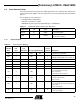
8. Mechanical Drawing
Note: (All dimensions are in mm)
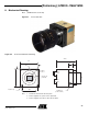
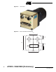
Figure 8-1. Front Panel View
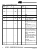
Figure 8-2. Front Panel Mechanical Drawing
Note: 1. A and B are mechanical reference plans
2. Sensor alignment ∆x, y refers to the optical axis
3. Sensor alignment ∆0
xy
refers to the reference plans
44.75
12
3.75
22
38.5
2 x (M4 x
8)
4 x (M3 x
8)
1 - 32 UN -
2A
(C mount)
First Pixel
of Line 1
B
A
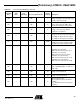
Camera
Link
Power
Supply
44
φ35
sensor
(on the 4 sides)