
User Manual


21
5429B–IMAGE–04/05
[Preliminary] ATMOS -1M60/1M30
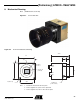
7. Connector Description
All connectors are on the rear panel. Better results are obtained by using shielded cables (foil
and braid shielded).
Note: cables for digital signals shall be twisted pairs.
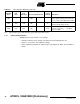
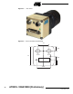
7.1 Power Supply
Camera connector type: Hirose HR10A-7R-6PB (male)
Cable connector type: Hirose HR10A-7P-6S (female)
Figure 7-1. Power Supply Pinout
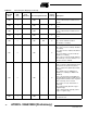
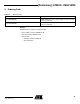
7.2 CameraLink Connector
Standard CameraLink cable shall be used to ensure the full electrical compatibility.
• Camera connector type: MDR-26 (female) ref. 3M 10226-2210VE
• We recommend to use a CameraLink standard shielded cable as 3M 14X26-SZLB-XXX-0LC
Figure 7-2. CameraLink Pinout
Power Connector : J01
Signal Pin Signal Pin
PWR 1 GND 4
NC 2 NC 5
PWR 3 GND 6
1
2
3
6
5
4
Receptacle Viewed from Camera Back
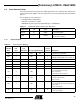
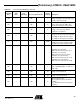
Command and Control Connector : J02
Signal Pin Signal Pin
GND 1 GND 14
X0- 2 X0+ 15
X1- 3 X1+ 16
X2- 4 X2+ 17
Xclk- 5 Xclk+ 18
X3- 6 X3+ 19
SerTC+ 7 SerTC- 20
SerTFG- 8 SerTFG+ 21
CC1- 9 CC1+ 22
CC2+ 10 CC2- 23
CC3- 11 CC3+ 24
CC4+ 12 CC4- 25
GND 13 GND 26