
Manual


111
8052B–AVR–09/08
ATmega4HVD/8HVD
Notes: 1. The actual value depends on the actual frequency of the ”Ultra Low Power RC Oscillator” on
page 24. See ”Electrical Characteristics” on page 142.
2. Initial value.
3. An additional delay up to T
d
can be expected after enabling the corresponding FET. This is
related to the initialization of the protection circuitry. For the Discharge Over-Current protec-
tion, this applies when enabling the Discharge FET. For Charge Over-Current protection,
this applies when enabling the Charge FET. With nominal ULP frequency this delay is maxi-
mum 0.2 ms.
Note: Due to synchronization of parameters between clock domains, a guard time of 3 ULP oscillator
cycles + 3 CPU clock cycles is required between each time the BPOCTR register is written. Any
writing to the BPOCTR register during this period will be ignored.
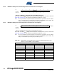
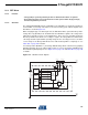
20.8.5 BPSCD – Battery Protection Short-circuit Detection Level Register
• Bits 7:0 – SCDL7:0: Short-circuit Detection Level
These bits sets the R
SENSE
voltage level for detection of Short-circuit in the discharge direction,
as defined in Table 20-4 on page 112. This register should always be written as one-hot.
Note: Due to synchronization of parameters between clock domains, a guard time of 3 ULP oscillator
cycles + 3 CPU clock cycles is required between each time the BPSCD register is written. Any
writing to the BPSCD register during this period will be ignored.
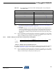
Table 20-3. Over-current Protection Reaction Time. OCPT[5:0] with corresponding Over-
current Delay Time.
Over-current Protection Reaction Time
(1)
OCPT[5:0] Typ
0x00 (0.0 - 0.5 ms) + T
d
(3)
0x01 (0.0 - 0.5 ms) + T
d
(3)
0x02
(2)
(0.5 - 1.0 ms) + T
d
(3)
0x03 (1.0 - 1.5 ms) + T
d
(3)
... ...
0x3E (30.5 - 31.0 ms) + T
d
(3)
0x3F (31.0 - 31.5 ms) + T
d
(3)
Bit 76543210
SCDL[7:0] BPSCD
Read/Write R/W R/W R/W R/W R/W R/W R/W R/W
Initial Value 0 0 0 0 0 0 0 1