
Manual


Table Of Contents
- Ordering Information
- Features
- Description
- Architectural Overview
- General Purpose Register File
- ALU - Arithmetic Logic Unit
- ISP Flash Program Memory
- SRAM Data Memory
- Program and Data Addressing Modes
- Register Direct, Single Register Rd
- Register Direct, Two Registers Rd and Rr
- I/O Direct
- Data Direct
- Data Indirect with Displacement
- Data Indirect
- Data Indirect With Pre-Decrement
- Data Indirect With Post-Increment
- Constant Addressing Using the LPM and ELPM Instructions
- Direct Program Address, JMP and CALL
- Indirect Program Addressing, IJMP and ICALL
- Relative Program Addressing, RJMP and RCALL
- EEPROM Data Memory
- Memory Access Times and Instruction Execution Timing
- I/O Memory
- Reset and Interrupt Handling
- Reset Sources
- Power-On Reset
- External Reset
- Watchdog Reset
- MCU Status Register - MCUSR
- Interrupt Handling
- External Interrupt Mask Register - EIMSK
- External Interrupt Flag Register - EIFR
- External Interrupt Control Register - EICR
- Timer/Counter Interrupt Mask Register - TIMSK
- Timer/Counter Interrupt Flag Register - TIFR
- Interrupt Response Time
- Sleep Modes
- Timer/Counters
- Timer/Counter Prescalers
- 8-bit Timer/Counters T/C0 and T/C2
- Timer/Counter0 Control Register - TCCR0
- Timer/Counter2 Control Register - TCCR2
- Timer/Counter0 - TCNT0
- Timer/Counter2 - TCNT2
- Timer/Counter0 Output Compare Register - OCR0
- Timer/Counter2 Output Compare Register - OCR2
- Timer/Counter 0 and 2 in PWM mode
- Asynchronous Status Register - ASSR
- Asynchronous Operation of Timer/Counter0
- 16-bit Timer/Counter1
- Timer/Counter1 Control Register A - TCCR1A
- Timer/Counter1 Control Register B - TCCR1B
- Timer/Counter1 - TCNT1H and TCNT1L
- Timer/Counter1 Output Compare Register - OCR1AH and OCR1AL
- Timer/Counter1 Output Compare Register - OCR1BH and OCR1BL
- Timer/Counter1 Input Capture Register - ICR1H and ICR1L
- Timer/Counter1 in PWM mode
- Watchdog Timer
- EEPROM Read/Write Access
- Serial Peripheral Interface - SPI
- UART
- Analog Comparator
- Analog to Digital Converter
- Interface to external SRAM
- I/O-Ports
- Memory Programming
- Electrical Characteristics
- Typical characteristics
- Register Summary
- Instruction Set Summary (Continued)
ATmega603/103
93
Signature Bytes
All Atmel microcontrollers have a three-byte signature code which identifies the device. This code can be read in both serial
and parallel mode. The three bytes reside in a separate address space.
For the ATmega603 they are:
1. $000: $1E (indicates manufactured by Atmel)
2. $001: $96 (indicates 64 Kb Flash memory)
3. $002: $01 (indicates ATmega603 when signature byte $001 is $96)
For the ATmega103 they are:
1. $000: $1E (indicates manufactured by Atmel)
2. $001: $97 (indicates 128 Kb Flash memory)
3. $002: $01 (indicates ATmega103 when signature byte $001 is $97)
Programming the Flash and EEPROM
Atmel’s ATmega603/103 offers 64K/128K bytes of in-system reprogrammable Flash memory and 2K/4K bytes of EEPROM
Data memory.
The ATmega603/103 is shipped with the on-chip Flash Program and EEPROM Data memory arrays in the erased state
(i.e. contents = $FF) and ready to be programmed. This device supports a High-Voltage (12V) Parallel programming mode
and a Low-Voltage Serial programming mode. The +12V supplied is used for programming enable only, and no current of
significance is drawn by this pin. The serial programming mode provides a convenient way to download program and data
into the ATmega603/103 inside the user’s system.
The Flash Program memory array on the ATmega603/103 is organized as 256/512 pages of 256 bytes each. When pro-
gramming the Flash, the program data is latched into a page buffer. This allows one page of program data to be
programmed simultaneously in either programming mode.
The EEPROM Data memory array on the ATmega603/103 is programmed byte-by-byte in either programming mode. An
auto-erase cycle is provided within the self-timed EEPROM write instruction in the serial programming mode.
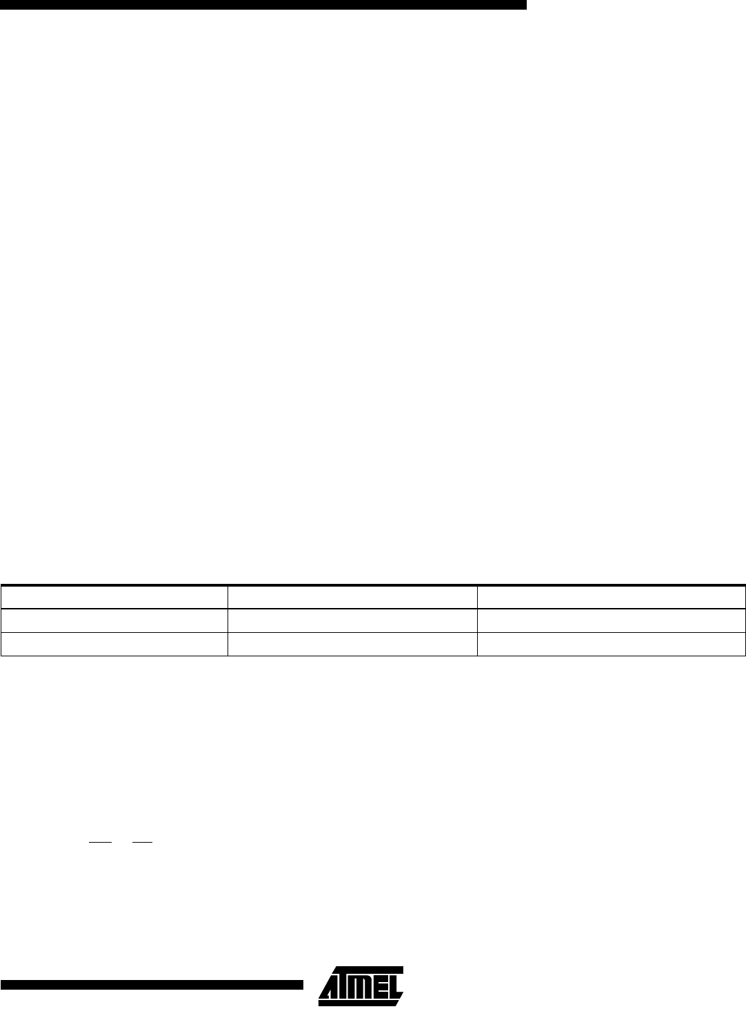
During programming, the supply voltage must be in accordance with Table 37
Table 37. Supply voltage during programming
Parallel Programming
This section describes how to parallel program and verify Flash Program memory, EEPROM Data memory, Lock bits and
Fuse bits in the ATmega603/103. Pulses are assumed to be at least 500 ns unless otherwise noted.
Signal Names
In this section, some pins of the ATmega603/103 are referenced by signal names describing their function during parallel
programming, see Figure 72 and Table 38. Pins not described in Table 38 are referenced by pin names.
The XA1/XA0 pins determine the action executed when the XTAL1 pin is given a positive pulse. The bit coding are shown
in Table 39.
When pulsing WR
or OE, the command loaded determines the action executed. The Command is a byte where the differ-
ent bits are assigned functions as shown in Table 40.
Part Serial programming Parallel programming
ATmega103/603 4.0 - 5.0 V 4.0 - 5.0 V
ATmega103L/603L 3.4 - 3.6 V 3.4 - 5.0 V