
Manual


Table Of Contents
- Ordering Information
- Features
- Description
- Architectural Overview
- General Purpose Register File
- ALU - Arithmetic Logic Unit
- ISP Flash Program Memory
- SRAM Data Memory
- Program and Data Addressing Modes
- Register Direct, Single Register Rd
- Register Direct, Two Registers Rd and Rr
- I/O Direct
- Data Direct
- Data Indirect with Displacement
- Data Indirect
- Data Indirect With Pre-Decrement
- Data Indirect With Post-Increment
- Constant Addressing Using the LPM and ELPM Instructions
- Direct Program Address, JMP and CALL
- Indirect Program Addressing, IJMP and ICALL
- Relative Program Addressing, RJMP and RCALL
- EEPROM Data Memory
- Memory Access Times and Instruction Execution Timing
- I/O Memory
- Reset and Interrupt Handling
- Reset Sources
- Power-On Reset
- External Reset
- Watchdog Reset
- MCU Status Register - MCUSR
- Interrupt Handling
- External Interrupt Mask Register - EIMSK
- External Interrupt Flag Register - EIFR
- External Interrupt Control Register - EICR
- Timer/Counter Interrupt Mask Register - TIMSK
- Timer/Counter Interrupt Flag Register - TIFR
- Interrupt Response Time
- Sleep Modes
- Timer/Counters
- Timer/Counter Prescalers
- 8-bit Timer/Counters T/C0 and T/C2
- Timer/Counter0 Control Register - TCCR0
- Timer/Counter2 Control Register - TCCR2
- Timer/Counter0 - TCNT0
- Timer/Counter2 - TCNT2
- Timer/Counter0 Output Compare Register - OCR0
- Timer/Counter2 Output Compare Register - OCR2
- Timer/Counter 0 and 2 in PWM mode
- Asynchronous Status Register - ASSR
- Asynchronous Operation of Timer/Counter0
- 16-bit Timer/Counter1
- Timer/Counter1 Control Register A - TCCR1A
- Timer/Counter1 Control Register B - TCCR1B
- Timer/Counter1 - TCNT1H and TCNT1L
- Timer/Counter1 Output Compare Register - OCR1AH and OCR1AL
- Timer/Counter1 Output Compare Register - OCR1BH and OCR1BL
- Timer/Counter1 Input Capture Register - ICR1H and ICR1L
- Timer/Counter1 in PWM mode
- Watchdog Timer
- EEPROM Read/Write Access
- Serial Peripheral Interface - SPI
- UART
- Analog Comparator
- Analog to Digital Converter
- Interface to external SRAM
- I/O-Ports
- Memory Programming
- Electrical Characteristics
- Typical characteristics
- Register Summary
- Instruction Set Summary (Continued)
ATmega603/103
2
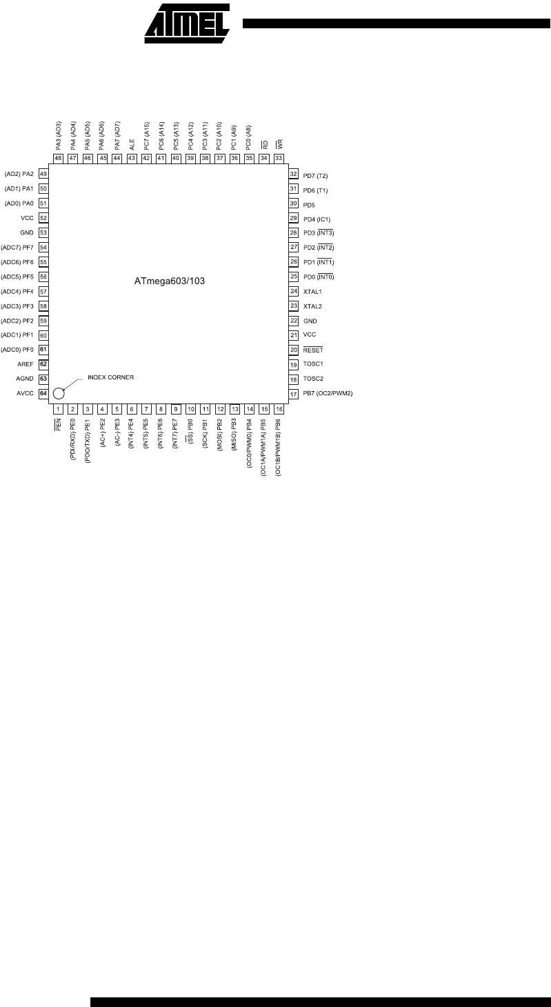
Pin Configuration
TQFP
Description
The ATmega603/103 is a low-power CMOS 8-bit microcontroller based on the AVR RISC architecture. By executing
powerful instructions in a single clock cycle, the ATmega603/103 achieves throughputs approaching 1 MIPS per MHz
allowing the system designer to optimize power consumption versus processing speed.
The AVR core is based on an enhanced RISC architecture that combines a rich instruction set with 32 general purpose
working registers. All the 32 registers are directly connected to the Arithmetic Logic Unit (ALU), allowing two independent
registers to be accessed in one single instruction executed in one clock cycle. The resulting architecture is more code
efficient while achieving throughputs up to ten times faster than conventional CISC microcontrollers.
The ATmega603/103 provides the following features: 64K/128K bytes of In-system Programmable Flash, 2K/4K bytes
EEPROM, 4K bytes SRAM, 32 general purpose I/O lines, 8 Input lines, 8 Output lines, 32 general purpose working regis-
ters, Real Time Counter (RTC), 4 flexible timer/counters with compare modes and PWM, UART, programmable Watchdog
Timer with internal oscillator, an SPI serial port and three software selectable power saving modes. The Idle Mode stops
the CPU while allowing the SRAM, timer/counters, SPI port and interrupt system to continue functioning. The Power Down
mode saves the register contents but freezes the oscillator, disabling all other chip functions until the next interrupt or hard-
ware reset. In Power Save mode, the timer oscillator continues to run, allowing the user to maintain a timer base while the
rest of the device is sleeping.
The device is manufactured using Atmel’s high-density nonvolatile memory technology. The on-chip ISP Flash allows the
program memory to be reprogrammed in-system through a serial interface or by a conventional nonvolatile memory pro-
grammer. By combining an 8-bit RISC CPU with a large array of ISP Flash on a monolithic chip, the Atmel ATmega603/103
is a powerful microcontroller that provides a highly flexible and cost effective solution to many embedded control
applications.
The ATmega603/103 AVR is supported with a full suite of program and system development tools including: C compilers,
macro assemblers, program debugger/simulators, in-circuit emulators, and evaluation kits.