
Manual


Table Of Contents
- Ordering Information
- Features
- Description
- Architectural Overview
- General Purpose Register File
- ALU - Arithmetic Logic Unit
- ISP Flash Program Memory
- SRAM Data Memory
- Program and Data Addressing Modes
- Register Direct, Single Register Rd
- Register Direct, Two Registers Rd and Rr
- I/O Direct
- Data Direct
- Data Indirect with Displacement
- Data Indirect
- Data Indirect With Pre-Decrement
- Data Indirect With Post-Increment
- Constant Addressing Using the LPM and ELPM Instructions
- Direct Program Address, JMP and CALL
- Indirect Program Addressing, IJMP and ICALL
- Relative Program Addressing, RJMP and RCALL
- EEPROM Data Memory
- Memory Access Times and Instruction Execution Timing
- I/O Memory
- Reset and Interrupt Handling
- Reset Sources
- Power-On Reset
- External Reset
- Watchdog Reset
- MCU Status Register - MCUSR
- Interrupt Handling
- External Interrupt Mask Register - EIMSK
- External Interrupt Flag Register - EIFR
- External Interrupt Control Register - EICR
- Timer/Counter Interrupt Mask Register - TIMSK
- Timer/Counter Interrupt Flag Register - TIFR
- Interrupt Response Time
- Sleep Modes
- Timer/Counters
- Timer/Counter Prescalers
- 8-bit Timer/Counters T/C0 and T/C2
- Timer/Counter0 Control Register - TCCR0
- Timer/Counter2 Control Register - TCCR2
- Timer/Counter0 - TCNT0
- Timer/Counter2 - TCNT2
- Timer/Counter0 Output Compare Register - OCR0
- Timer/Counter2 Output Compare Register - OCR2
- Timer/Counter 0 and 2 in PWM mode
- Asynchronous Status Register - ASSR
- Asynchronous Operation of Timer/Counter0
- 16-bit Timer/Counter1
- Timer/Counter1 Control Register A - TCCR1A
- Timer/Counter1 Control Register B - TCCR1B
- Timer/Counter1 - TCNT1H and TCNT1L
- Timer/Counter1 Output Compare Register - OCR1AH and OCR1AL
- Timer/Counter1 Output Compare Register - OCR1BH and OCR1BL
- Timer/Counter1 Input Capture Register - ICR1H and ICR1L
- Timer/Counter1 in PWM mode
- Watchdog Timer
- EEPROM Read/Write Access
- Serial Peripheral Interface - SPI
- UART
- Analog Comparator
- Analog to Digital Converter
- Interface to external SRAM
- I/O-Ports
- Memory Programming
- Electrical Characteristics
- Typical characteristics
- Register Summary
- Instruction Set Summary (Continued)
ATmega603/103
103
7. Any memory location can be verified by using the Read instruction which returns the content at the selected
address at serial output PE1(PDO/TXD).
8. At the end of the programming session, RESET
can be set high to commence normal operation.
9. Power-off sequence (if needed): Set XTAL1 to ‘0’ (if a crystal is not used). Set RESET
to ‘1’. Turn VCC power off
Table 43 shows the actual delays used in this section.
Please NOTE: The MISO pin is not Hi-Z during serial programming.
Data Polling for the EEPROM
When a new EEPROM byte has been written and is being programmed into the EEPROM, reading the address location
being programmed will give the value P1 (please refer to Table 44.) until the auto-erase is finished, and then the value P2.
At the time the device is ready for a new EEPROM byte, the programmed value will read correctly. This is used to deter-
mine when the next byte can be written. This will not work for the values P1 and P2, so when programming these values,
the user will have to wait for at least the prescribed time
t
WD_EEPROM
(please refer to Table 43) before programming the next
byte. As a chip-erased device contains $FF in all locations, programming of addresses that are meant to contain $FF, can
be skipped. This does not apply if the EEPROM is reprogrammed without chip erasing the device.
Data polling is not implemented for the Flash!
Note: See Errata sheet for latest information.
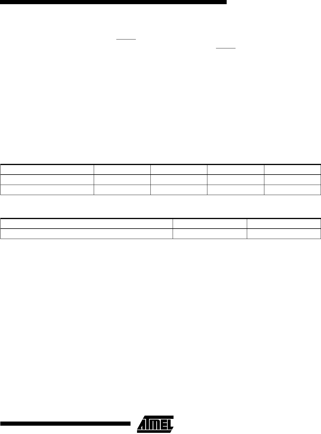
Table 43. Minimum wait delay before writing the next Flash or EEPROM location
Symbol 3.2V 3.6V 4.0V 5.0V
t
WD_FLASH
56 ms 43 ms 35 ms 22 ms
t
WD_EEPROM
9 ms 7 ms 6 ms 4 ms
Table 44. Read back value during EEPROM polling
Part/Revision P1 P2
TBD TBD TBD