
Manual


5
4912C–AUTO–10/06
ATA6827 [Preliminary]
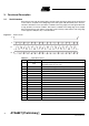
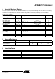
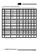
Table 3-2. Output Data Protocol
Bit
Output (Status)
Register Function
0 TP Temperature prewarning: high = warning
1
Status LS1 High = output is on, low = output is off; not affected by SRR
2
Status HS1 High = output is on, low = output is off; not affected by SRR
3
Status LS2 Description see LS1
4
Status HS2 Description see HS1
5
Status LS3 Description see LS1
6
Status HS3 Description see HS1
7
n. u. Not used
8
n. u. Not used
9
n. u. Not used
10
n. u. Not used
11
n. u. Not used
12
n. u. Not used
13
SCD
Short circuit detected: set high when at least one high-side or low-side
switch is switched off by a short-circuit condition. Bits 1 to 6 can be used
to detect the shorted switch.
14
OPL
Open load detected: set high, when at least one active high-side or
low-side switch sinks/sources a current below the open load threshold
current.
15
PSF Power-supply fail: undervoltage at pin VS detected
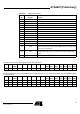
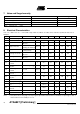
After power-on reset, the input register has the following status:
Bit 15 Bit 14 Bit 13
(OCS)
Bit 12 Bit 11 Bit 10 Bit 9 Bit 8 Bit 7 Bit 6
(HS3)
Bit 5
(LS3)
Bit 4
(HS2)
Bit 3
(LS2)
Bit 2
(HS1)
Bit 1
(LS1)
Bit 0
(SRR)
xxHxxxxxxLLLLLLL
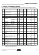
The following patterns are used to enable internal test modes of the IC. It is not recommended to use these patterns during
normal operation.
Bit 15 Bit 14 Bit 13
(OCS)
Bit 12 Bit 11 Bit 10 Bit 9 Bit 8 Bit 7 Bit 6
(HS3)
Bit 5
(LS3)
Bit 4
(HS2)
Bit 3
(LS2)
Bit 2
(HS1)
Bit 1
(LS1)
Bit 0
(SRR)
HHHHHLLLLLLLLLLL
HHHLLHHLLLLLLLLL
HHHLLLLHHLLLLLLL