
User guide

8
ATA5811/ATA5812 [Preliminary]
4689B–RKE–04/04
Typical Key Fob Application, 2 Batteries
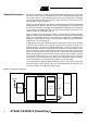
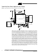
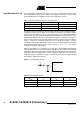
Figure 6. Typical RKE Key Fob Application, 433.92 MHz, 2 Batteries
Figure 6 shows a typical 433.92 MHz 2-battery RKE key fob or sensor application. The
external components are 11 capacitors, 1 resistor, 2 inductors and a crystal. C
1
and C
4
are 68 nF voltage supply blocking capacitors. C
2
and C
3
are 2.2 µF supply blocking
capacitors for the internal voltage regulators. C
5
is a 10 nF supply blocking capacitor. C
6
is a 15 nF fixed capacitor used for the internal quasi peak detector and for the highpass
frequency of the data filter. C
7
to C
11
are RF matching capacitors in the range of 1 pF to
33 pF. L
1
is a matching inductor of about 5.6 nH to 56 nH. L
2
is a feed inductor of about
120 nH. A load capacitor for the crystal of 9 pF is integrated. R
1
is typically 22 kΩ and
sets the output power to about 5.5 dBm.
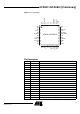
AVCC
RX_TX1
RX_TX2
DVCC
VS2
VS1
VSINT
VAUX
PWR_ON
N_RESET
XTAL1
XTAL2
CLK
TEST1
DEM_OUT
T1
T2
T3
T4
T5
IRQ
RSSI
CDEM
CS
SCK
SDI_TMDI
SDO_TMDO
VSOUT
NC
RX_ACTIVE
RF_IN
NC
NC
R_PWR
RF_OUT
433_N868
PWR_H
NC
NC
NC
NC
NC
NC
NC
TEST2
NC
NC
NC
VCC
VSS
AVCC
20 mm x 0.4 mm
Loop antenna
Microcontroller
ATA5811/ATA5812
Litihum Cells
C
1
C
2
C
9
C
8
C
10
C
5
C
11
C
6
C
3
+
L
1
L
2
C
4
R
1
13.25311 MHz
C
7
+