
User guide

47
ATA5811/ATA5812 [Preliminary]
4689B–RKE–04/04
.
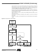
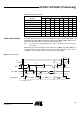
4-wire Serial Interface The 4-wire serial interface consists of the Chip Select (CS), the Serial ClocK (SCK), the
Serial Data Input (SDI_TMDI) and the Serial Data Output (SDO_TMDO). Data is trans-
mitted/received bit by bit in synchronization with the serial clock.
Note: If the output level on pin N_RESET is low, no data communication with the microcontrol-
ler is possible.
When CS is low and the transparent mode is inactive (T_MODE = 0), SDO_TMDO is in
a high-impedance state. When CS is low and the transparent mode is active
(T_MODE = 1), the RX data stream is available on pin SDO_TMDO.
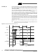
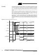
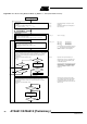
Figure 39. Serial Timing
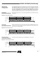
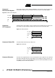
Table 36. Command Structure
Command
MSB LSB
Bit 7 Bit 6 Bit 5 Bit 4 Bit 3 Bit 2 Bit 1 Bit 0
Read TX/RX data buffer 0 0 0 x x x x x
Write TX/RX data buffer 0 0 1 x x x x x
Read control/status register 0 1 0 A4 A3 A2 A1 A0
Write control register 0 1 1 A4 A3 A2 A1 A0
OFF command 100XXXXX
Delete IRQ 1 0 1 X X X X X
Not used 1 1 0 X X X X X
Not used 1 1 1 X X X X X
CS
SCK
SDI_TMDI
SDO_TMDO
T
Out_enable
T
Setup
XMSB
T
Hold
X
MSB
T
Cycle
T
CS_setup
MSB-1
T
Out_delay
MSB-1
X
T
CS_disable
T
Out_disable
X
LSB
X
X
T
SCK_setup1
T
SCK_setup2
T
SCK_hold
X can be either V
il
or V
iH