
User guide

4
ATA5811/ATA5812 [Preliminary]
4689B–RKE–04/04
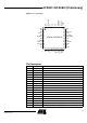
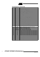
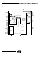
19 VAUX Auxiliary supply voltage input
20 TEST1 Test input, at GND during operation
21 DVCC Blocking of the digital voltage supply
22 VSOUT Output voltage power supply for external devices
23 TEST2 Test input, at GND during operation
24 XTAL1 Reference crystal
25 XTAL2 Reference crystal
26 NC Not connected
27 VSINT Microcontroller Interface supply voltage
28 N_RESET Output pin to reset a connected microcontroller
29 IRQ Interrupt request
30 CLK Output to clock a connected microcontroller
31 SDO_TMDO Serial data out/transparent mode data out
32 SDI_TMDI Serial data in/transparent mode data in
33 SCK Serial clock
34 DEM_OUT Demodulator open drain output signal
35 CS Chip select for serial interface
36 RSSI Output of the RSSI amplifier
37 CDEM Capacitor to adjust the lower cut-off frequency data filter
38 RX_TX2 GND pin to decouple LNA in TX mode
39 RX_TX1 Switch pin to decouple LNA in TX mode
40 PWR_ON Input to switch on the system (active high)
41 T1 Key input 1 (can also be used to switch on the system (active low)
42 T2 Key input 2 (can also be used to switch on the system (active low)
43 T3 Key input 3 (can also be used to switch on the system (active low)
44 T4 Key input 4 (can also be used to switch on the system (active low)
45 T5 Key input 5 (can also be used to switch on the system (active low)
46 RX_ACTIVE Indicates RX operation mode
47 NC Not connected
48 NC Not connected
GND Ground/backplane
Pin Description (Continued)
Pin Symbol Function