
User guide

39
ATA5811/ATA5812 [Preliminary]
4689B–RKE–04/04
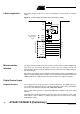
Status Register The status register indicates the current status of the transceiver and is readable via the
4-wire serial interface. Setting Power_On or P_On_Aux or an event on ST1, ST2, ST3,
ST4 or ST5 is indicated by an IRQ.
Reading the status register resets the bits Power_On, Low_Batt, P_On_Aux and the
IRQ
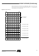
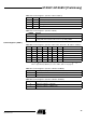
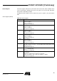
Status Register (ADR 8)
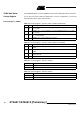
Table 35. Status Register
Status Bit Function
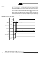
ST5 Status of pin T5
Pin T5 = 0 → ST5 = 1
Pin T5 = 1 → ST5 = 0
(see Figure 29 on page 41)
ST4 Status of pin T4
Pin T4 = 0 → ST4 = 1
Pin T4 = 1 → ST4 = 0
(see Figure 29 on page 41)
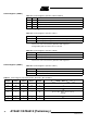
ST3 Status of pin T3
Pin T3 = 0 → ST3 = 1
Pin T3 = 1 → ST3 = 0
(see Figure 29 on page 41)
ST2 Status of pin T2
Pin T2 = 0 → ST2 = 1
Pin T2 = 1 → ST2 = 0
(see Figure 29 on page 41)
ST1 Status of pin T1
Pin T1 = 0 → ST1 = 1
Pin T1 = 1 → ST1 = 0
(see Figure 29 on page 41)
Power_On
Indicates that the transceiver was woken up by pin PWR_ON (rising edge on pin
PWR_ON). During Power_On = 1, the bits VSOUT_EN and CLK_ON in control
register 3 are set to 1.
(see Figure 30 on page 42)
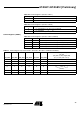
Low_Batt Indicates that output voltage on pin VSOUT is too low
(V
VSOUT
< 2.38 V typically)
(see Figure 31 on page 43)
P_On_Aux Indicates that the auxiliary supply voltage on pin VAUX is high enough to operate.
State transition:
a) OFF mode → AUX mode (see Figure 22 on page 28)
b) Idle mode (VSOUT = VS1) → Idle mode (VSOUT = V_REG2)
(see Figure 32 on page 44)