
User guide

34
ATA5811/ATA5812 [Preliminary]
4689B–RKE–04/04
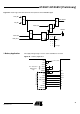
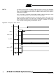
TX/RX Data Buffer The TX/RX data buffer is used to handle the data transfer during RX and TX operations.
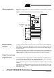
Control Register To use the transceiver in different applications it can be configured by a connected
microcontroller via the 4-wire serial interface.
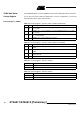
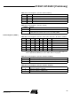
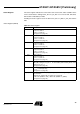
Control Register 1 (ADR 0)
Table 14. Control Register 1 (Function of Bit 7 and Bit 6 in RX Mode)
IR1 IR0 Function (RX Mode)
00
Pin IRQ is set to 1 if 4 received bytes are in the TX/RX data buffer or a receiving
error occurred
01
Pin IRQ is set to 1 if 8 received bytes are in the TX/RX data buffer or a receiving
error occurred
10
Pin IRQ is set to 1 if 12 received bytes are in the TX/RX data buffer or a receiving
error occurred (default)
1 1 Pin IRQ is set to 1 if a receiving error occurred
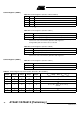
Table 15. Control Register 1 (Function of Bit 7 and Bit 6 in TX Mode)
IR1 IR0 Function (TX Mode)
00
Pin IRQ is set to 1 if 4 bytes still are in the TX/RX data buffer or the TX data buffer
is empty
01
Pin IRQ is set to 1 if 8 bytes still are in the TX/RX data buffer or the TX data buffer
is empty
10
Pin IRQ is set to 1 if 12 bytes still are in the TX/RX data buffer or the TX data buffer
is empty (default)
1 1 Pin IRQ is set to 1 if the TX data buffer is empty
Table 16. Control Register 1 (Function of Bit 5)
AVCC_EN Function
0 (default)
1 Enables AVCC, if the ATA5811/
ATA5812 is in AUX mode
Table 17. Control Register 1 (Function of Bit 4)
FS Function
0 433/868 MHz
1315 MHz