
Owner's manual


6
9167AS–RFID–11/09
ATA5575M1 [Preliminary]
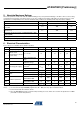
7.1 Clock detection level V
coil pp
= 8V V
clkdet
TBD 550 TBD mV T
7.2 Gap detection level V
coil pp
= 8V V
gapdet med
TBD 550 TBD mV T
8 Programming time
From last command gap
to re-enter read mode
(64 + 648 internal clocks)
T
prog
55.76msT
9 Endurance Erase all / write all
(3)
n
cycle
100000 Cycles Q
10.1
Data retention
Top = 55°C
(3)
t
retention
10 20 50 Years Q
10.2 Top = 150°C
(3)
t
retention
96 hrs T
10.3 Top = 250°C
(3)
t
retention
24 hrs Q
11.1
Resonance capacitor
Mask option
(4)
V
coil pp
= 1V
C
r
TBD 330 TBD
pF T
11.2 TBD 250 TBD
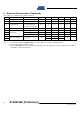
6. Electrical Characteristics (Continued)
T
amb
= +25°C; f
coil
= 125 kHz; unless otherwise specified
No. Parameters Test Conditions Symbol Min. Typ. Max. Unit Type*
*) Type means: T: directly or indirectly tested during production; Q: guaranteed based on initial product qualification data
Notes: 1. I
DD
measurement setup: EEPROM programmed to 00 ... 000 (erase all); chip in modulation defeat.
2. Current into Coil1/Coil2 is limited to 10 mA.
3. Since the EEPROM performance is influenced by assembly processes, Atmel can not confirm the parameters for -DDW
(tested die on unsawn wafer) delivery.