
Owner's manual


5
9167AS–RFID–11/09
ATA5575M1 [Preliminary]
t
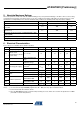
5. Absolute Maximum Ratings
Stresses beyond those listed under “Absolute Maximum Ratings” may cause permanent damage to the device. This is a stress rating
only and functional operation of the device at these or any other conditions beyond those indicated in the operational sections of this
specification is not implied. Exposure to absolute maximum rating conditions for extended periods may affect device reliability.
Parameters Symbol Value Unit
Maximum DC current into Coil1/Coil2 I
coil
TBD mA
Maximum AC current into Coil1/Coil2
f = 125 kHz
I
coil p
TBD mA
Power dissipation (dice) (free-air condition, time of
application: 1s)
P
tot
TBD mW
Electrostatic discharge maximum to ANSI/ESD-STM5.1-2001
standard (HBM)
V
max
TBD V
Operating ambient temperature range T
amb
–40 to +85 °C
Storage temperature range (data retention reduced) T
stg
–40 to +150 °C
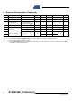
6. Electrical Characteristics
T
amb
= +25°C; f
coil
= 125 kHz; unless otherwise specified
No. Parameters Test Conditions Symbol Min. Typ. Max. Unit Type*
1 RF frequency range f
RF
100 125 150 kHz
2.1
Supply current
(without current
consumed by the external
LC tank circuit)
T
amb
= 25°C
(1)
I
DD
1.5 3 µA T
2.2
Read – full temperature
range
25µAQ
2.3
Programming – full
temperature range
25 µA Q
3.1
Coil voltage (AC supply)
Read mode and write
command
(2)
V
coil pp
6V
clamp
VQ
3.2 Program EEPROM
(2)
16 V
clamp
VQ
4 Start-up time V
coil pp
= 6V t
startup
1.1 ms Q
5.1
Clamp
3 mA current into Coil1/2 V
pp
TBD 17 TBD V T
5.2 20 mA current into Coil1/2 V
pp
TBD 20 TBD V T
6.1
Modulation parameters
3 mA current into Coil1/2
and modulation ON
V
pp
TBD 7 TBD V Q
6.2
20 mA current into Coil1/2
and modulation ON
V
pp
TBD 9 TBD V T
6.3 Thermal stability V
mod lo
/T
amb
–1 mV/°C Q
*) Type means: T: directly or indirectly tested during production; Q: guaranteed based on initial product qualification data
Notes: 1. I
DD
measurement setup: EEPROM programmed to 00 ... 000 (erase all); chip in modulation defeat.
2. Current into Coil1/Coil2 is limited to 10 mA.
3. Since the EEPROM performance is influenced by assembly processes, Atmel can not confirm the parameters for -DDW
(tested die on unsawn wafer) delivery.