
Owner manual


AT90C8534
35
the corresponding interrupt handling vector. Alternatively, ADIF is cleared by writing a logical “1” to the flag. Beware that if
doing a read-modify-write on ADCSR, a pending interrupt can be disabled. This also applies if the SBI or CBI instructions
are used.
•
Bit 3 – ADIE: ADC Interrupt Enable
When this bit is set (one) and the I-bit in SREG is set (one), the ADC Conversion Complete Interrupt is activated.
•
Bits 2..0 – ADPS2..ADPS0: ADC Prescaler Select Bits
These bits determine the division factor between the XTAL frequency and the input clock to the ADC.
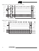
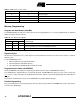
ADC Data Register – ADCL AND ADCH
When an ADC conversion is complete, the result is found in these two registers. In Free Run Mode, it is essential that both
registers are read, and that ADCL is read before ADCH.
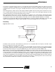
Scanning Multiple Channels
Since change of analog channel always is delayed until a conversion is finished, the Free Run Mode can be used to scan
multiple channels without interrupting the converter. Typically, the ADC Conversion Complete interrupt will be used to
perform the channel shift. However, the user should take the following fact into consideration:
The interrupt triggers once the result is ready to be read. In Free Run Mode, the next conversion will start immediately
when the interrupt triggers. If ADMUX is changed after the interrupt triggers, the next conversion has already started and
the old setting is used.
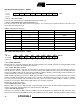
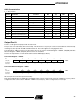
Table 8. ADC Prescaler Selections
ADPS2 ADPS1 ADPS0 Division Factor
000 2
001 2
010 4
011 8
100 16
101 32
110 64
111 128
Bit 151413121110 9 8
$05 ($25) ––––––ADC9 ADC8 ADCH
$04 ($24) ADC7 ADC6 ADC5 ADC4 ADC3 ADC2 ADC1 ADC0 ADCL
76543210
Read/Write RRRRRRRR
RRRRRRRR
Initial value 8 0 0 0 0 0 0 0
80000000