
User Manual


98
8111A–AVR–05/08
AT86RF231
register bit is automatically cleared after requesting a CCA measurement with
CCA_REQUEST = 1.
• Bit [6:5] - CCA_MODE
The CCA mode can be selected using register bits CCA_MODE.
Note that IEEE 802.15.4-2006 CCA Mode 3 defines the logical combination of CCA Mode 1 and
2 with the logical operators AND or OR. This can be selected with:
• Bit [4:0] - CHANNEL
Refer to Section 9.7 “Frequency Synthesizer (PLL)” on page 121.
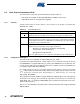
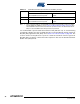
Register 0x09 (CCA_THRES):
This register sets the ED threshold level for CCA.
• Bit [7:5] - Reserved
• Bit [4:0] - CCA_ED_THRES
The CCA Mode 1 request indicates a busy channel if the measured received power is above
RSSI_BASE_VAL + 2 * CCA_ED_THRES [dBm]. CCA Modes 0 and 3 are logical related to this
result.
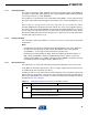
Table 8-12. CCA Status Result
Register Bit Value State Description
CCA_MODE 0 Mode 3a, Carrier sense OR energy above threshold
1 Mode 1, Energy above threshold
2 Mode 2, Carrier sense only
3 Mode 3b, Carrier sense AND energy above threshold
•CCA_MODE = 0
for logical operation OR, and
•CCA_MODE = 3
for logical operation AND.
Bit 7 6 5 4 3 2 1 0
+0x09 Reserved CCA_ED_THRES CCA_THRES
Read/Write R/W R/W R/W R/W R/W R/W R/W R/W
Reset Value 1 1 0 0 0 1 1 1