
User Manual


97
8111A–AVR–05/08
AT86RF231
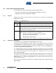
8.5.6 Register Description
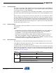
Register 0x01 (TRX_STATUS):
Two register bits of register 0x01 (TRX_STATUS) signal the status of the CCA measurement.
• Bit 7 - CCA_DONE
This register indicates if a CCA request is completed. This is also indicated by an interrupt
IRQ_4 (CCA_ED_READY). Note, register bit CCA_DONE is cleared in response to a
CCA_REQUEST.
• Bit 6 - CCA_STATUS
After a CCA request is completed the result of the CCA measurement is available in register bit
CCA_STATUS. Note, register bit CCA_STATUS is cleared in response to a CCA_REQUEST.
• Bit 5 - Reserved
• Bit [4:0] - TRX_STATUS
Refer to Section 7.1.5 “Register Description” on page 44 and Section 7.2.7 “Register Descrip-
tion - Control Registers” on page 68.
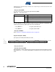
Register 0x08 (PHY_CC_CCA):
This register is provided to initiate and control a CCA measurement.
• Bit 7 - CCA_REQUEST
A manual CCA measurement is initiated with setting CCA_REQUEST = 1. The end of the CCA
measurement is indicated by interrupt IRQ_4 (CCA_ED_READY). Register bits CCA_DONE
and CCA_STATUS (register 0x01, TRX_STATUS) are updated after a CCA_REQUEST. The
Bit 7 6 5 4 3 2 1 0
+0x01 CCA_DONE CCA_STATUS Reserved TRX_STATUS TRX_STATUS
Read/Write R R R R R R R R
Reset Value 0 0 0 0 0 0 0 0
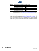
Table 8-10. CCA Algorithm Status
Register Bit Value State Description
CCA_DONE 0
CCA calculation not finished
1 CCA calculation finished
Table 8-11. CCA Status Result
Register Bit Value State Description
CCA_STATUS 0
Channel indicated as busy
1 Channel indicated as idle
Bit 7 6 5 4 3 2 1 0
+0x08 CCA_REQUEST CCA_MODE CHANEL PHY_CC_CCA
Read/Write W R/W R/W R/W R/W R/W R/W R/W
Reset Value 0 0 1 0 1 0 1 1