
User Manual


90
8111A–AVR–05/08
AT86RF231
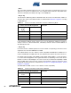
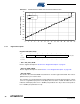
Figure 8-4. Mapping between RSSI Value and Received Input Power
8.3.4 Register Description
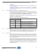
Register 0x06 (PHY_RSSI):
• Bit 7 - RX_CRC_VALID
Refer to register description in Section 8.2.5 “Register Description” on page 87.
• Bit [6:5] - RND_VALUE
Refer to register description in section Section 11.2.2 “Register Description” on page 136.
• Bit [4:0] - RSSI
The result of the automated RSSI measurement is stored in register bits RSSI. The value is
updated every 2 µs in receive states.
The read value is a number between 0 and 28 indicating the received signal strength as a linear
curve on a logarithmic input power scale (dBm) with a resolution of 3 dB. An RSSI value of 0
indicates an RF input power of P
RF
< -90 dBm (see parameter 12.7.16), a value of 28 a power of
P
RF
≥ 10 dBm (see parameter 12.7.18).
-100
-90
-80
-70
-60
-50
-40
-30
-20
-10
0
10
0 2 4 6 8 1012141618202224262830
RSSI
Receiver Input Power P
RF
[dBm]
Measured
Ideal
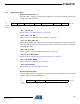
Bit 7 6 5 43210
+0x06 RX_CRC_VALID RND_VALUE RSSI PHY_RSSI
Read/Write R R R RRRRR
Reset Value 0 0 0 0 0 0 0 0