
User Manual


42
8111A–AVR–05/08
AT86RF231
/RST = L sets all registers to their default values. Exceptions are register bits CLKM_CTRL (reg-
ister 0x03, TRX_CTRL_0), refer to Section 9.6.4 “Master Clock Signal Output (CLKM)” on page
117.
After releasing the reset pin (/RST = H) the wake-up sequence including an FTN calibration
cycle is performed, refer to Section 9.8 “Automatic Filter Tuning (FTN)” on page 125. After that
the TRX_OFF state is entered.
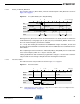
Figure 7-7 on page 41 illustrates the reset procedure once the P_ON state was left and the radio
transceiver was not in SLEEP state.
The reset procedure is identical for all originating radio transceiver states except of state P_ON
and SLEEP state. Instead, here the procedure described in Section 7.1.2.1 “P_ON - Power-On
after VDD” on page 34 must be followed to enter the TRX_OFF state.
If the radio transceiver was in SLEEP state, the XOSC and DVREG are enabled before entering
TRX_OFF state.
If register TRX_STATUS indicates STATE_TRANSITION_IN_PROGRESS during system initial-
ization until the AT86RF231 reaches TRX_OFF, do not try to initiate a further state change while
the radio transceiver is in this state.
Notes
• The reset impulse should have a minimum length t
10
= 625 ns as specified in Section 12.4
“Digital Interface Timing Characteristics” on page 157, see parameter 12.4.13.
• An access to the device should not occur earlier than t
11
≥ 625 ns after releasing the pin
/RST; refer to Section 12.4 “Digital Interface Timing Characteristics” on page 157, parameter
12.4.14.
• A reset overrides an SPI command request that might be queued.
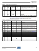
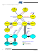
7.1.4.6 State Transition Timing Summary
The transition numbers correspond to Figure 7-1 on page 33 and do not include SPI access time
if not otherwise stated. See measurement setup in Figure 5-1 on page 12.
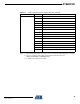
Table 7-1. State Transition Timing
No Symbol Transition Time [µs], (type) Comments
1t
TR1
P_ON
until CLKM
available
380
Depends on external capacitor at DVDD (1 µF nom) and crystal
oscillator setup (CL = 10 pF)
2t
TR2
SLEEP TRX_OFF 240
Depends on external capacitor at DVDD (1 µF nom) and crystal
oscillator setup (CL = 10 pF)
TRX_OFF state indicated by IRQ_4 (AWAKE_END)
3t
TR3
TRX_OFF SLEEP 35*1/f
CLKM
For f
CLKM
> 250 kHz
4
t
TR4
TRX_OFF PLL_ON 110 Depends on external capacitor at AVDD (1 µF nom)
5t
TR5
PLL_ON TRX_OFF 1
6t
TR6
TRX_OFF RX_ON 110 Depends on external capacitor at AVDD (1 µF nom)
7t
TR7
RX_ON TRX_OFF 1
8t
TR8
PLL_ON RX_ON 1
9t
TR9
RX_ON PLL_ON 1 Transition time is also valid for TX_ARET_ON, RX_AACK_ON
⇒
⇒
⇒
⇒
⇒
⇒
⇒
⇒
⇒