
User Manual


41
8111A–AVR–05/08
AT86RF231
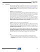
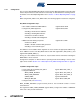
7.1.4.4 BUSY_TX and RX_ON States
The transition from PLL_ON to BUSY_TX state and subsequent to RX_ON state is shown in
Figure 7-6 on page 41.
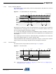
Figure 7-6. PLL_ON to BUSY_TX to RX_ON Timing
Starting from PLL_ON state it is further assumed that the PLL is already locked. A transmission
is initiated either by a rising edge of pin 11 (SLP_TR) or by command TX_START. The PLL set-
tles to the transmit frequency and the PA is enabled.
t
TR10
= 16 µs after initiating the transmission the AT86RF231 changes into BUSY_TX state and
the internally generated SHR is transmitted. After that the PSDU data are transmitted from the
Frame Buffer.
After completing the frame transmission, indicated by IRQ_3 (TRX_END), the PLL settles back
to the receive frequency within t
TR11
= 32 µs in state PLL_ON.
If during TX_BUSY the radio transmitter is programmed to change to a receive state it automati-
cally proceeds the state change to RX_ON state after finishing the transmission.
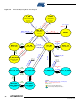
7.1.4.5 Reset Procedure
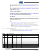
The radio transceiver reset procedure is shown in Figure 7-7 on page 41.
Figure 7-7. Reset Procedure
Note: Timing figure t
TR13
refers to Table 7-1 on page 42, t
10
, t
11
refers to Section 12.4 “Digital Interface
Timing Characteristics” on page 157.
Time [µs]0x16 x + 32
Time
t
TR11
t
TR10
Command
RX_ON
State
Block
PLL_ON RX_ONBUSY_TX
Pin
SLP_TR
PA PLLPA, TX RXPLL
or command TX_START
x
Event
State
Block
Time [µs]
Pin /RST
TRX_OFF
x + 40
[IRQ_4 (AWAKE_END)]
0
various
Time
>t10 t
TR13
>t11
XOSC, DVREG XOSC, DVREG
x + 10
FTN