
User Manual


31
8111A–AVR–05/08
AT86RF231
Register 0x04 (TRX_CTRL_1):
The TRX_CTRL_1 register is a multi purpose register to control various operating modes and
settings of the radio transceiver.
• Bit 7 - PA_EXT_EN
Refer to Section 11.5 “RX/TX Indicator” on page 147.
• Bit 6 - IRQ_2_EXT_EN
The timing of a received frame can be determined by a separate pin. If register bit
IRQ_2_EXT_EN is set to 1, the reception of a PHR is directly issued on pin 10 (DIG2), similar to
interrupt IRQ_2 (RX_START). Note that this pin is also active even if the corresponding interrupt
event IRQ_2 (RX_START) mask bit in register 0x0E (IRQ_MASK) is set to 0. The pin remains at
high level until the end of the frame receive procedure.
For further details refer to Section 11.6 “RX Frame Time Stamping” on page 150.
• Bit 5 - TX_AUTO_CRC_ON
Refer to Section 8.2 “Frame Check Sequence (FCS)” on page 85.
• Bit 4 - RX_BL_CTRL
Refer to Section 11.7 “Frame Buffer Empty Indicator” on page 152.
• Bit [3:2] - SPI_CMD_MODE
Refer to Section 6.3 “Radio Transceiver Status information” on page 24.
• Bit 1 - IRQ_MASK_MODE
The AT86RF231 supports polling of interrupt events. Interrupt polling can be enabled by register
bit IRQ_MASK_MODE. Even if an interrupt request is masked by the corresponding bit in regis-
ter 0x0E (IRQ_MASK), the event is indicated in register 0x0F (IRQ_STATUS).
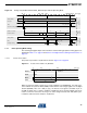
Bit 7 6 5 4 3 2 1 0
+0x04 PA_EXT_EN IRQ_2_EXT_EN TX_AUTO_CRC_ON RX_BL_CTRL SPI_CMD_MODE IRQ_MASK_MODE IRQ_POLARITY TRX_CTRL_1
Read/Write R/W R/W R/W R/W R/W R/W R/W R/W
Reset Value 0 0 1 0 0 0 0 0
Table 6-10. Interrupt Polling Configuration
Register Bit Value Description
IRQ_MASK_MODE 0
Interrupt polling disabled
1 Interrupt polling enabled