
User Manual

3
8111A–AVR–05/08
AT86RF231
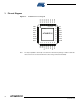
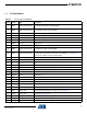
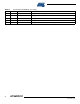
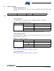
1.1 Pin Descriptions
Table 1-1. Pin Description AT86RF231
Pins Name Type Description
1 DIG3 Digital output (Ground)
1. RX/TX Indicator, see Section 11.5
2.
If disabled, pull-down enabled (AVSS)
2 DIG4 Digital output (Ground)
1. RX/TX indicator (DIG3 inverted), see Section 11.5
2. If disabled, pull-down enabled (AVSS)
3 AVSS Ground Ground for RF signals
4 RFP RF I/O Differential RF signal
5 RFN RF I/O Differential RF signal
6 AVSS Ground Ground for RF signals
7 DVSS Ground Digital ground
8 /RST Digital input Chip reset; active low
9 DIG1 Digital output (Ground)
1. Antenna Diversity RF switch control, see Section 11.4
2. If disabled, pull-down enabled (DVSS)
10 DIG2 Digital output (Ground)
1. Antenna Diversity RF switch control (DIG1 inverted), see Section 11.4
2. Signal IRQ_2 (RX_START) for RX Frame Time Stamping, see Section 11.6
3. If functions disabled, pull-down enabled (DVSS)
11 SLP_TR Digital input Controls sleep, transmit start, receive states; active high, see Section 6.5
12 DVSS Ground Digital ground
13 DVDD Supply Regulated 1.8V voltage regulator; digital domain, see Section 9.4
14 DVDD Supply Regulated 1.8V voltage regulator; digital domain, see Section 9.4
15 DEVDD Supply External supply voltage; digital domain
16 DVSS Ground Digital ground
17 CLKM Digital output Master clock signal output; low if disabled, see Section 9.6
18 DVSS Ground Digital ground
19 SCLK Digital input SPI clock
20 MISO Digital output SPI data output (Master Input Slave Output)
21 DVSS Ground Digital ground
22 MOSI Digital input SPI data input (Master Output Slave Input)
23 /SEL Digital input SPI select, active low
24 IRQ Digital output
1. Interrupt request signal; active high or active low; configurable
2. Frame Buffer Empty Indicator; active high, see Section 11.7
25 XTAL2 Analog input Crystal pin, see Section 9.6
26 XTAL1 Analog input Crystal pin or external clock supply, see Section 9.6
27 AVSS Ground Analog ground
28 EVDD Supply External supply voltage, analog domain