
User Manual


24
8111A–AVR–05/08
AT86RF231
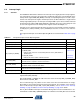
6.3 Radio Transceiver Status information
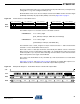
Each SPI access can be configured to return status information of the radio transceiver
(PHY_STATUS) to the microcontroller using the first byte of the data transferred via MISO.
The content of the radio transceiver status information can be configured using register bits
SPI_CMD_MODE (register 0x04, TRX_CTRL_1). After reset, the content on the first byte send
on MISO to the microcontroller is set to 0x00.
6.3.1 Register Description - SPI Control
Register 0x04 (TRX_CTRL_1):
The TRX_CTRL_1 register is a multi purpose register to control various operating modes and
settings of the radio transceiver.
• Bit 7 - PA_EXT_EN
Refer to Section 11.5 “RX/TX Indicator” on page 147.
• Bit 6 - IRQ_2_EXT_EN
Refer to Section 11.6 “RX Frame Time Stamping” on page 150.
• Bit 5 - TX_AUTO_CRC_ON
Refer to Section 8.2 “Frame Check Sequence (FCS)” on page 85.
• Bit 4 - RX_BL_CTRL
Refer to Section 11.7 “Frame Buffer Empty Indicator” on page 152.
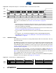
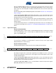
• Bit [3:2] - SPI_CMD_MODE
Each SPI transfer returns bytes back to the SPI master. The content of the first byte can be con-
figured using register bits SPI_CMD_MODE. The transfer of the following status information can
be configured as follows:
• Bit 1 - IRQ_MASK_MODE
Refer to Section 6.6 “Interrupt Logic” on page 29.
• Bit 0 - IRQ_POLARITY
Refer to Section 6.6 “Interrupt Logic” on page 29.
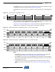
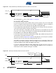
Bit 7 6 5 4 3 2 1 0
+0x04 PA_EXT_EN IRQ_2_EXT_EN TX_AUTO_CRC_ON RX_BL_CTRL SPI_CMD_MODE IRQ_MASK_MODE IRQ_POLARITY TRX_CTRL_1
Read/Write R/W R/W R/W R/W R/W R/W R/W R/W
Initial Value 0 0 1 0 0 0 0 0
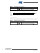
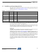
Table 6-3. Radio Transceiver Status Information - PHY_STATUS
Register Bit Value Description
SPI_CMD_MODE 0
default (empty, all bits 0x00)
1 monitor TRX_STATUS register; see Section 7.1.5
2 monitor PHY_RSSI register; see Section 8.3
3 monitor IRQ_STATUS register; see Section 6.6