
User Manual


22
8111A–AVR–05/08
AT86RF231
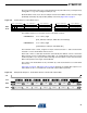
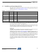
Figure 6-10. Example SPI Sequence - Frame Buffer Write of a Frame with 4 byte PSDU
Access violations during a Frame Buffer read or write access are indicated by interrupt IRQ_6
(TRX_UR). For further details, refer to Section 9.3 “Frame Buffer” on page 107.
Notes
• The Frame Buffer is shared between RX and TX; therefore, the frame data are overwritten by
new incoming frames. If the TX frame data are to be retransmitted, it must be ensured that no
frame was received in the meanwhile.
• To avoid overwriting during receive Dynamic Frame Buffer Protection can be enabled, refer to
Section 11.8 “Dynamic Frame Buffer Protection” on page 154.
• It is not possible to retransmit received frames without a Frame Buffer read and write access
cycle.
• For exceptions, e.g. receiving acknowledgement frames in Extended Operating Mode
(TX_ARET) refer to Section 7.2.4 “TX_ARET_ON - Transmit with Automatic Retry and
CSMA-CA Retry” on page 64.
6.2.3 SRAM Access Mode
The SRAM access mode allows accessing dedicated bytes within the Frame Buffer. This may
reduce the SPI traffic.
The SRAM access mode is useful, for instance, if a transmit frame is already stored in the Frame
Buffer and dedicated bytes (e.g. sequence number, address field) need to be replaced before
retransmitting the frame. Furthermore, it can be used to access only the LQI value after frame
reception. A detailed description of the user accessible frame content can be found in Section
9.3 “Frame Buffer” on page 107.
Each SRAM access starts with /SEL = L. The first transferred byte on MOSI shall be the com-
mand byte and must indicate an SRAM access mode according to the definition in Table 6-2 on
page 19. The following byte indicates the start address of the write or read access. The address
space is 0x00 to 0x7F for radio transceiver receive or transmit operations.
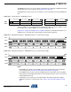
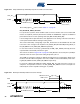
On SRAM read access, one or more bytes of read data are transferred on MISO starting with the
third byte of the access sequence (see Figure 6-11 on page 22).
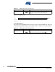
Figure 6-11. Packet Structure - SRAM Read Access
COMMAND PHR PSDU 1 PSDU 2 PSDU 3 PSDU 4
PHY_STATUS XX XXXX XXXX
SCLK
MOSI
MISO
/SEL
0 reserved[5:0]0MOSI
PHY_STATUSMISO
byte 1 (command byte)
0 ADDRESS[7:0]
XX
byte 2 (address)
XX
DATA[7:0]
byte 3 (data byte)
XX
DATA[7:0]
byte n-1 (data byte)
XX
DATA[7:0]
byte n (data byte)