
User Manual


21
8111A–AVR–05/08
AT86RF231
Note, the Frame Buffer read access can be terminated at any time without any consequences by
setting /SEL = H, e.g. after reading the PHR byte only.
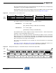
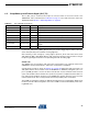
On Frame Buffer write access the second byte transferred on MOSI contains the frame length
(PHR field) followed by the payload data (PSDU) as shown by Figure 6-8 on page 21.
Figure 6-8. Packet Structure - Frame Write Access
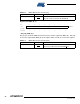
The number of bytes n for one frame access is calculated as follows:
The maximum value of frame_length is 127 bytes. That means that n ≤ 130 for Frame Buffer
read and n ≤ 129 for Frame Buffer write accesses.
Each read or write of a data byte increments automatically the address counter of the Frame
Buffer until the access is terminated by setting /SEL = H. A Frame Buffer read access may be
terminated (/SEL = H) at any time without affecting the Frame Buffer content. Another Frame
Buffer read operation starts again at the PHR field.
The content of the Frame Buffer is only overwritten by a new received frame or a Frame Buffer
write access.
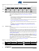
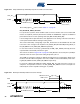
Figure 6-9 on page 21 and Figure 6-10 on page 22 illustrate an example SPI sequence of a
Frame Buffer access to read and write a frame with 4-byte PSDU respectively.
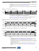
Figure 6-9. Example SPI Sequence - Frame Buffer Read of a Frame with 4-byte PSDU
0 reserved[5:0]1MOSI
PHY_STATUSMISO
byte 1 (command byte)
1 PHR[7:0]
XX
byte 2 (data byte)
PSDU[7:0]
XX
byte 3 (data byte)
PSDU[7:0]
XX
byte n-1 (data byte)
PSDU[7:0]
XX
byte n (data byte)
• Read Access:
n = 3 + frame_length
[PHY_STATUS, PHR byte, PSDU data, and LQI byte]
• Write Access:
n = 2 + frame_length
[command byte, PHR byte, and PSDU data]
COMMAND XX XX XX XX XX
PHY_STATUS PHR PSDU 2PSDU 1 PSDU 4PSDU 3
XX
LQI
SCLK
MOSI
MISO
/SEL