
User Manual

2
8111A–AVR–05/08
AT86RF231
1. Pin-out Diagram
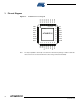
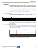
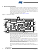
Figure 1-1. AT86RF231 Pin-out Diagram
Note: The exposed paddle is electrically connected to the die inside the package. It shall be soldered to
the board to ensure electrical and thermal contact and good mechanical stability.
32
24
23
22
21
20
19
18
17
1
2
3
4
5
6
7
8
AT
86
RF
231
CLKM
DVSS
DIG3
DIG4
AVSS
AVSS
RFP
RFN
DVSS
/R ST
DIG1
DIG2
SLP_TR
DVSS
DVDD
DVDD
DEVDD
DVSS
SCLK
MISO
DVSS
MOSI
/SEL
IR Q
XTAL2
XTAL1
AVSS
EVDD
AVDD
AVSS
AVSS
AVSS
31 30 29 28 27 26 25
9 10111213141516
AVSS
exposed paddle