
User Manual


172
8111A–AVR–05/08
AT86RF231
20. Appendix A - Continuous Transmission Test Mode
20.1 Overview
The AT86RF231 offers a Continuous Transmission Test Mode to support final application / pro-
duction tests as well as certification tests. Using this test mode the radio transceiver transmits
continuously a previously transferred frame (PRBS mode) or a continuous wave signal (CW
mode).
In CW mode two different signal frequencies per channel can be transmitted:
•f
1
= f
CH
+ 0.5 MHz
•f
2
= f
CH
- 0.5 MHz
Here f
CH
is the channel center frequency programmed by register 0x08 (PHY_CC_CCA).
Note, in CW mode it is not possible to transmit an RF signal directly on the channel center
frequency.
PSDU data in the Frame Buffer must contain at least a valid PHR (see Section 8.1 “Introduction
- IEEE 802.15.4 - 2006 Frame Format” on page 79). It is recommended to use a frame of maxi-
mum length (127 bytes) and arbitrary PSDU data for the PRBS mode. The SHR and the PHR
are not transmitted. The transmission starts with the PSDU data and is repeated continuously.
20.2 Configuration
Before enabling Continuous Transmission Test Mode all register configurations shall be done as
follow:
• TX channel setting (optional)
• TX output power setting (optional)
• Mode selection (PRBS / CW)
A register access to register 0x36 and 0x1C enables the Continuous Transmission Test Mode.
The transmission is started by enabling the PLL (TRX_CMD = PLL_ON) and writing the
TX_START command to register 0x02.
Even for CW signal transmission it is required to write valid PSDU data to the Frame Buffer. For
PRBS mode it is recommended to write a frame of maximum length.
The detailed programming sequence is shown in Table 20-1 on page 172. The column R/W
informs about writing (W) or reading (R) a register or the Frame Buffer.
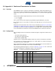
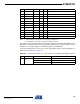
Table 20-1. Continuous Transmission Programming Sequence.
Step Action Register R/W Value Description
1 RESET Reset AT86RF231
2 Register Access 0X0E W 0x01 Set IRQ mask register, enable IRQ_0 (PLL_LOCK)
3 Register Access 0x04 W 0x00 Disable TX_AUTO_CRC_ON
4 Register Access 0x02 W 0x03 Set radio transceiver state TRX_OFF
5 Register Access 0x03 W 0x01 Set clock at pin 17 (CLKM)
6 Register Access 0x08 W 0x33 Set IEEE 802.15.4 CHANNEL, e.g. 19
7 Register Access 0x05 W 0x00 Set TX output power, e.g. to Pmax