
User Manual


17
8111A–AVR–05/08
AT86RF231
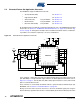
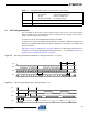
6.1 SPI Timing Description
Pin 17 (CLKM) can be used as a microcontroller master clock source. If the microcontroller
derives the SPI master clock (SCLK) directly from CLKM, the SPI operates in synchronous
mode, otherwise in asynchronous mode.
In synchronous mode, the maximum SCLK frequency is 8 MHz.
In asynchronous mode, the maximum SCLK frequency is limited to 7.5 MHz. The signal at pin
CLKM is not required to derive SCLK and may be disabled to reduce power consumption and
spurious emissions.
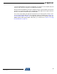
Figure 6-2 on page 17 and Figure 6-3 on page 17 illustrate the SPI timing and introduces its
parameters. The corresponding timing parameter definitions t
1
- t
9
are defined in Section 12.4
“Digital Interface Timing Characteristics” on page 157.
Figure 6-2. SPI Timing, Global Map and Definition of Timing Parameters t
5
, t
6
, t
8
and t
9
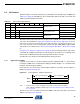
Figure 6-3. SPI Timing, Detailed Drawing of Timing Parameter t
1
to t
4
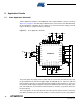
SLP_TR Multipurpose control signal (functionality is state dependent, see Section 6.5):
-Sleep/Wakeup enable/disable SLEEP state
-TX start BUSY_TX_(ARET) state
-disable/enable CLKM RX_(AACK)_ON state
/RST AT86RF231 reset signal, active low
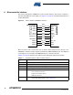
DIG2 Optional, IRQ_2 (RX_START) for RX Frame Time Stamping, see Section 11.6
Table 6-1. Signal Description of Microcontroller Interface (Continued)
SCLK
t
8
MOSI
67 5 4 3 2 1 0 67 5 4 3 2 1 0
MISO
Bit 6 Bit 5 Bit 3 Bit 2 Bit 1 Bit 0Bit 4 Bit 6 Bit 5 Bit 3 Bit 2 Bit 1 Bit 0Bit 4Bit 7
t
6
Bit 7
t
5
/SEL
t
9
Bit 7 Bit 6
t
1
t
2
Bit 5
t
4
t
3
Bit 7 Bit 6 Bit 5
SCLK
MOSI
MISO
/SEL