
User Manual


159
8111A–AVR–05/08
AT86RF231
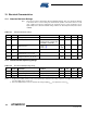
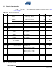
12.6 Transmitter Characteristics
Test Conditions (unless otherwise stated):
V
DD
= 3.0V, f
RF
= 2.45 GHz, T
OP
= 25°C, Measurement setup see Figure 5-1 on page 12.
Table 12-6. Transmitter Characteristics
No. Symbol Parameter Condition Min. Typ. Max Units
12.6.1 P
TX
TX Output power Maximum configurable TX output
power value
Register bit TX_PWR = 0
0+3+6dBm
12.6.2 P
RANGE
Output power range 16 steps, configurable in
register 0x05 (PHY_TX_PWR)
20 dB
12.6.3 P
ACC
Output power tolerance ±3 dB
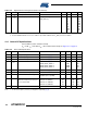
12.6.4 TX Return loss 100Ω differential impedance,
P
TX
= +3 dBm
10 dB
12.6.5 EVM 8%rms
12.6.6 P
HARM
Harmonics
2
nd
harmonic
3
rd
harmonic
-38
-45
dBm
dBm
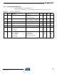
12.6.7 P
SPUR
Spurious Emissions
30 - ≤ 1000 MHz
>1 - 12.75 GHz
1.8 - 1.9 GHz
5.15 - 5.3 GHz
Complies with
EN 300 328/440,
FCC-CFR-47 part 15,
ARIB STD-66, RSS-210
-36
-30
-47
-47
dBm
dBm
dBm
dBm