
User Manual


123
8111A–AVR–05/08
AT86RF231
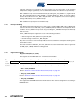
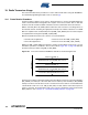
Register 0x1A (PLL_CF):
This register controls the operation of the center frequency calibration loop.
• Bit 7 - PLL_CF_START
PLL_CF_START = 1 initiates the center frequency calibration. The calibration cycle has finished
after t
TR21
= 35 µs (typ.). The register bit is cleared immediately after finishing the calibration.
• Bit [6:0] - Reserved
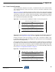
Register 0x1B (PLL_DCU):
This register controls the operation of the delay cell calibration loop.
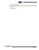
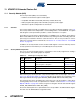
Table 9-17. Channel Assignment for IEEE 802.15.4 - 2.4 GHz Band
Register Bit Value Channel Number k Center Frequency [MHz]
CHANNEL 0x0B
11 2405
0x0C 12 2410
0x0D 13 2415
0x0E 14 2420
0x0F 15 2425
0x10 16 2430
0x11 17 2435
0x12 18 2440
0x13 19 2445
0x14 20 2450
0x15 21 2455
0x16 22 2460
0x17 23 2465
0x18 24 2470
0x19 25 2475
0x1A 26 2480
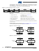
Bit 7 6 5 4 3 2 1 0
+0x1A PLL_CF_START Reserved PLL_CF
Read/Write R/W R/W R/W R/W R/W R/W R/W R/W
Reset Value 0 1 0 1 0 1 1 1
Bit 7 6 5 4 3 2 1 0
+0x1B PLL_DCU_START Reserved PLL_DCU
Read/Write R/W R R/W R/W R/W R/W R/W R/W
Reset Value 0 0 1 0 0 0 0 0